 Hyundai Azera: Repair procedures
Fifth generation HG (2011–2026) / Hyundai Azera 2011-2026 Service Manual / Body Electrical System / Smart key System / Repair procedures
Hyundai Azera: Repair procedures
Fifth generation HG (2011–2026) / Hyundai Azera 2011-2026 Service Manual / Body Electrical System / Smart key System / Repair procedures
Fifth generation HG (2011–2026) / Hyundai Azera 2011-2026 Service Manual / Body Electrical System / Smart key System / Repair procedures
| Inspection |
Self Diagnosis With GDS
Smart key system defects can be quickly diagnosed with the
GDS. GDS operates actuator quickly to monitor, input/output value and
self diagnosis.
The following three features will be major problem in SMART KEY system.
| 1. |
Problem in SMART KEY unit input. |
| 2. |
Problem in SMART KEY unit. |
| 3. |
Problem in SMART KEY unit output. |
The following three diagnostic solutions will be the main solution process to a majority of concerns.
| 1. |
SMART KEY unit Input problem : switch diagnosis |
| 2. |
SMART KEY unit problem : communication diagnosis |
| 3. |
SMART KEY unit Output problem : antenna and switch output diagnosis |
Switch Diagnosis
| 1. |
Connect the cable of GDS to the data link connector in driver side crash pad lower panel, turn the power on GDS. |
| 2. |
Select the vehicle model and then SMART KEY system.
|
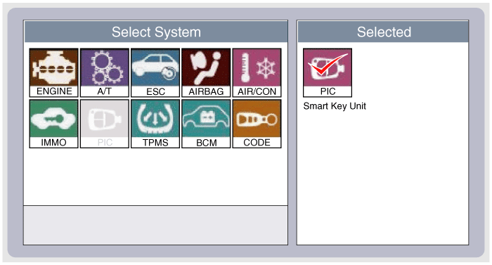
| 3. |
Select the "SMART KEY unit". |
| 4. |
After IG ON, select the "Current data".
|
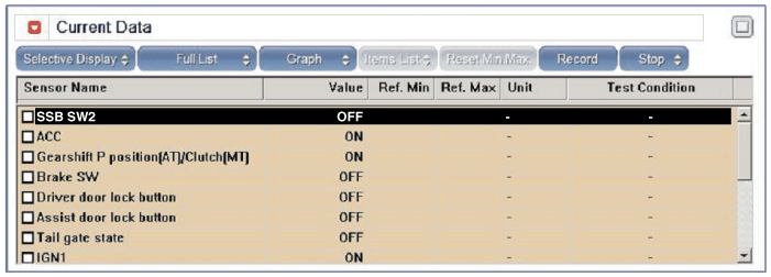
| 5. |
You can see the situation of each switch on scanner after connecting the "current data" process.
|
Communication Diagnosis With GDS (Self Diagnosis)
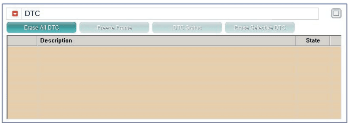
| 1. |
Communication diagnosis checks that the each linked components operates normal. |
| 2. |
Connect the cable of GDS to the data link connector in driver side crash pad lower panel. |
| 3. |
After IG ON, select the "DTC".
|
Antenna Actuation Diagnosis
| 1. |
Connect the cable of GDS to the data link connector in driver side crash pad lower panel. |
| 2. |
After IG ON, select the "ACTUATION TEST".
|
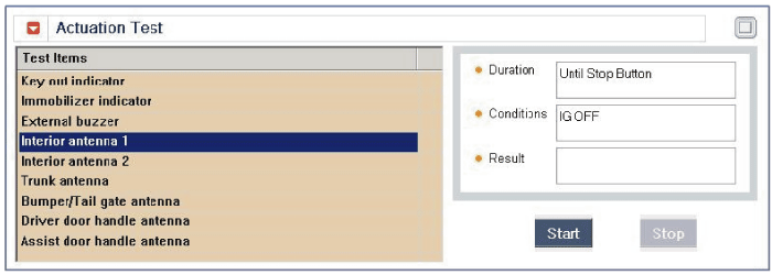
| 3. |
Set the smart key near the related antenna and operate it with a GDS.
|

| 4. |
If the LED of smart key is blinking, the smart key is normal. |
| 5. |
If the LED of smart key is not blinking, check the voltage of smart key battery. |
| 6. |
Antenna actuation
|
Antenna Status Check
| 1. |
Connect the cable of GDS to the data link connector in driver side crash pad lower panel. |
| 2. |
Select the "Antenna Status Check".
|
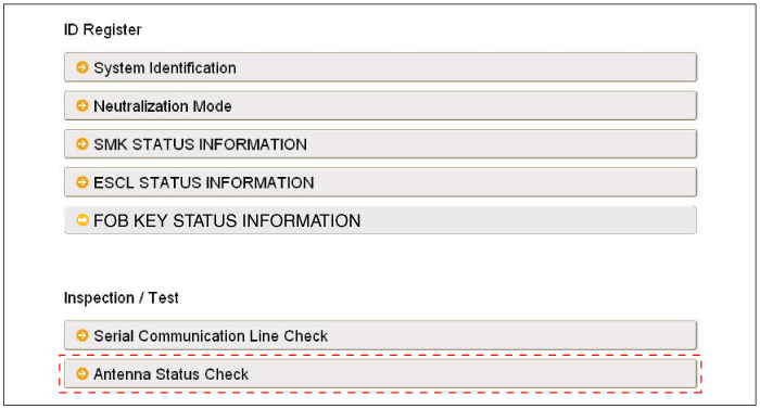
| 3. |
After IG ON, select the "Antenna Status Check".
|

| 4. |
Set the smart key near the related antenna and operate it with a GDS.
|
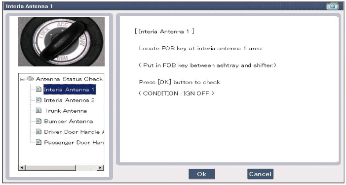
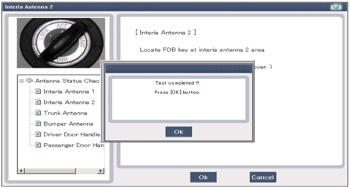
| 5. |
If the smart key runs normal , the related antenna, smart key(transmission, reception) and exterior receiver are normal. |
| 6. |
Antenna status
|
Serial Communication Status Check
| 1. |
Connect the cable of GDS to the data link connector in driver side crash pad lower panel. |
| 2. |
Select the "Serial Communication Line Check".
|
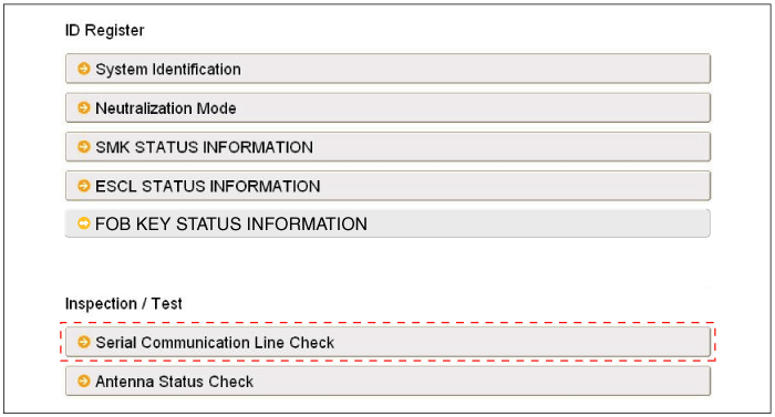
| 3. |
After IGN ON, select the "Receiver Communication Line Check".
|
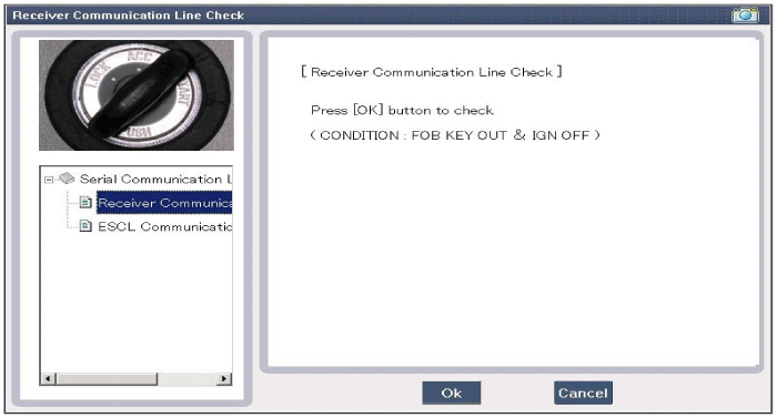
| 4. |
Check the serial communication line with a GDS. |
| 5. |
If the receiver communication line runs normal, check the "ESCL Communication Line Check".
|
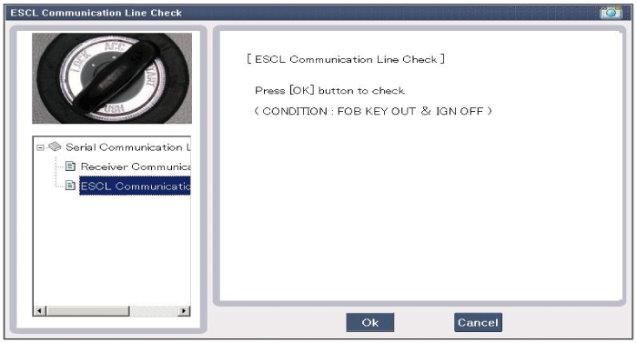
| 6. |
If the smart key runs normal, the communication of smart key unit, exterior receiver and ESCL are normal. |
| 7. |
If the smart key runs abnormal, check the following items.
|
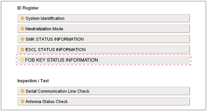
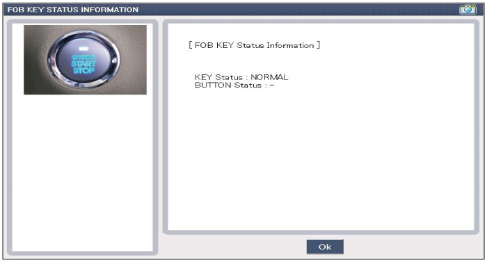
FOB Status Check
| 1. |
Connect the cable of GDS to the data link connector in driver side crash pad lower panel. |
| 2. |
After IGN ON, select the "FOB KEY STATUS INFO".
|
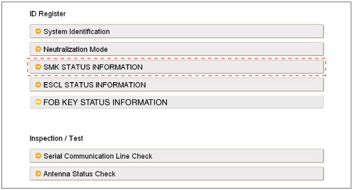
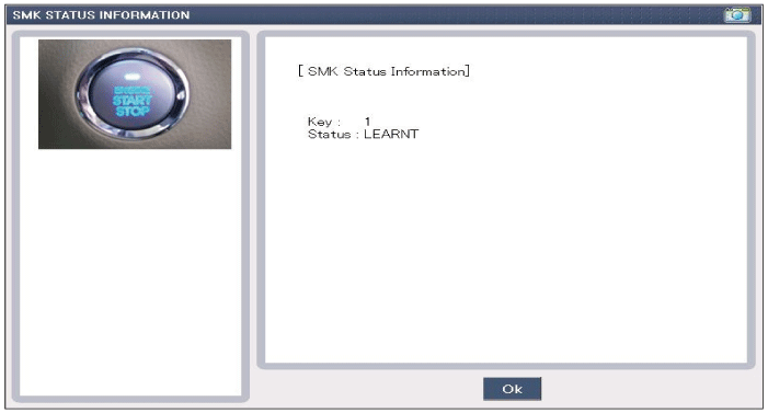
Smart Key Status Check
| 1. |
Connect the cable of GDS to the data link connector in driver side crash pad lower panel. |
| 2. |
After IGN ON, select the "SMK STATUS INFO".
|
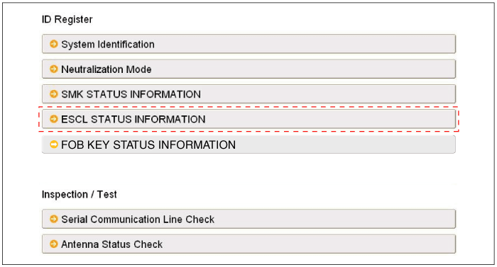
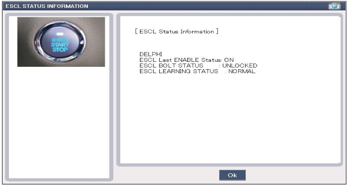
ESCL Status Check
| 1. |
Connect the cable of GDS to the data link connector in driver side crash pad lower panel. |
| 2. |
After IG ON, select the "ESCL STATUS INFO".
|
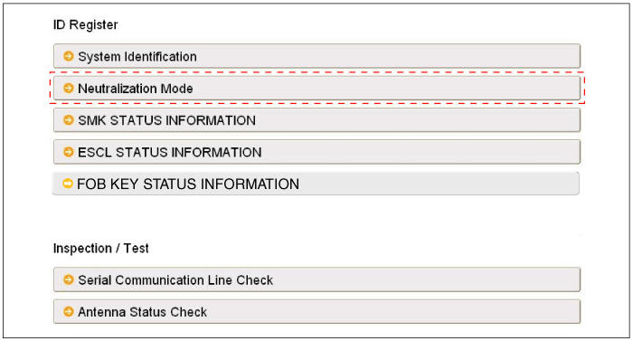
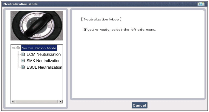
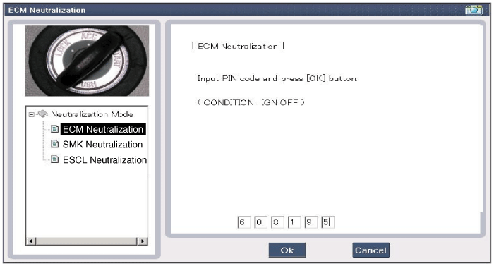
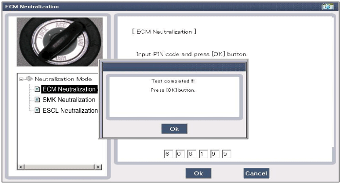
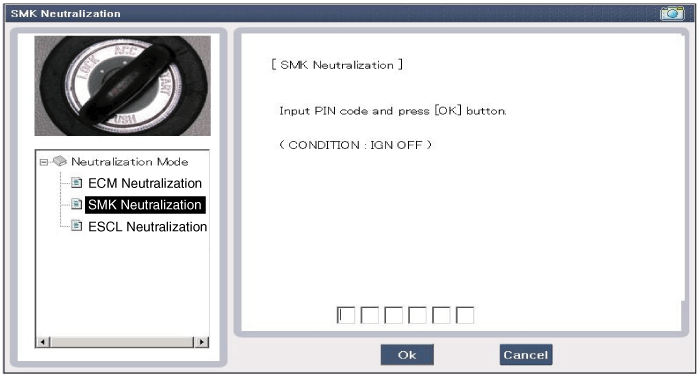
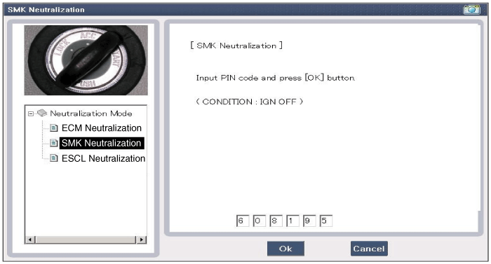
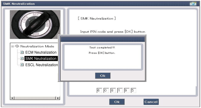
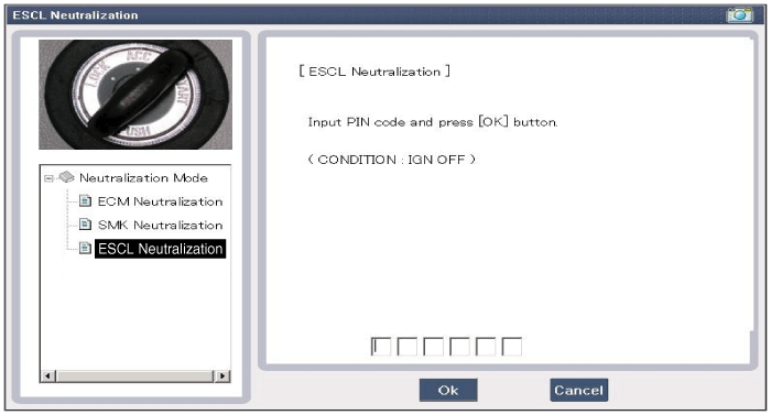
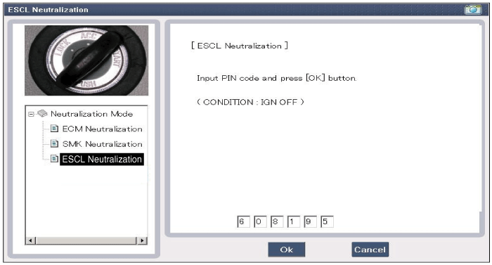
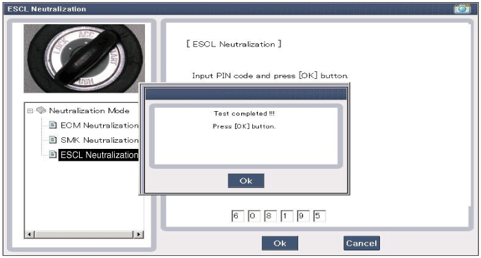
Neutralization Status Check
| 1. |
Connect the cable of GDS to the data link connector in driver side crash pad lower panel. |
| 2. |
After IGN ON, select the "Neutralization mode".
|
Input Switch List
| No | Item name | Unit |
| 1 | SSB switch2 | - |
| 2 | ACC | - |
| 3 | IGN1 | - |
| 4 | Gear 'P' Position | - |
| 5 | Brake switch | - |
| 6 | FL Door Lock Button | - |
| 7 | FR Door Lock Button | - |
| 8 | Trunk Lid switch | - |
| 9 | Battery Voltage | - |
| 10 | Alternator Voltage | - |
| 11 | KEY out Indicator Lamp | - |
| 12 | Immobilizer Lamp | - |
| 13 | External Buzzer | - |
| 14 | ESCL Enable | - |
Actuator List
| No. | Item name | Condition |
| 1 | Immo.indicator Lamp | Ignition switch ON Engine off |
| 2 | External Buzzer | Ignition switch ON Engine off |
| 3 | Interior Antenna 1 Active | Ignition switch ON Engine off |
| 4 | Interior Antenna 2 Active | Ignition switch ON Engine off |
| 5 | Trunk Antenna Active | Ignition switch ON Engine off |
| 6 | Bumper Antenna Active | Ignition switch ON Engine off |
| 7 | DRV DR Antenna Active | Ignition switch ON Engine off |
| 8 | AST DR Antenna Active | Ignition switch ON Engine off |
 Description and Operation
Description
Communication network diagram
AbbreviationExplanationC_CANChassis Controller Area NetworkB_CANBody Controller Area NetworkMM_CANMulti media Controller Area NetworkSMKSmart Key ECUDDM ...
 Smart key Repair procedures
Smart Key
Smart Key Code Saving
1.
Connect the DLC cable of GDS to the data link connector in driver side crash pad lower panel, turn the power on GDS.
2.
Select the vehicle model and then do ...
See also:
Door lock/unlock features
Impact sensing door unlock system
All doors will automatically unlock when an impact causes the air bags to deploy.
Shift lever door lock/unlock system
All doors will automatically lock when the ...
SRS care
The SRS is virtually maintenance-free and so there are no parts you can safely
service by yourself. If the SRS air bag warning light (
) does not illuminate when you turn
the ignition ON, or if it ...
ICM (Integrated Circuit Module) Relay Box Repair procedures
Inspection
Two Turn Unlock Relay
Check for continuity between the terminals.
1.
There should be continuity between the No.18 and No.17
terminals when power and ground are connected to the No. ...
Categories
Hyundai Azera Manuals

© 2011-2026 Copyright www.hgmanual.com