| Compression Pressure Inspection |
|
If the there is lack of power, excessive oil consumption or poor fuel economy, measure the compression pressure. |
| 1. |
Warm up engine until the normal operating temperature(80~95°C(176-203°F)). |
| 2. |
Remove the surge tank.
(Refer to Intake And Exhaust System - "Surge Tank") |
| 3. |
Remove the ignition coils.
|
| 4. |
Remove the spark plugs.
|
| 5. |
Check cylinder compression pressure.
| (1) |
Insert a compression gauge into the spark plug hole. |
| (2) |
Fully open the throttle. |
| (3) |
Crank the engine over 7 times to measure compression pressure.
|
Always use a fully charged battery to obtain engine speed of 250 rpm or more. |
|
| (4) |
Repeat step 1) though 3) for each cylinder.
|
This measurement must be done in as short a time as possible. |
Compression pressure :
1,029kPa (10.5kgf/cm?, 149psi) (250~400 rpm)
Minimum pressure :
882kPa (9.0kgf/cm?, 128psi)
Difference between each cylinder :
98kPa (1.0kg/cm?, 14psi) or less
|
|
| (5) |
If the cylinder compression in 1 or more cylinders is low,
pour a small amount of engine oil into the cylinder through the spark
plug hole and repeat step 1) through 3) for cylinders with low
compression.
| A. |
If adding oil helps the compression, it is likely that the piston rings and/or cylinder bore are worn or damaged. |
| B. |
If pressure stays low, a valve may be sticking or seating is improper, or there may be leakage past the gasket. |
|
|
| 6. |
Reinstall the spark plugs. |
| 7. |
Install the ignition coils and ignition connectors. |
| 8. |
Install the surge tank.
(Refer to Intake And Exhaust System - "Surge Tank") |
Valve Clearance Inspection And Adjustment
|
Inspect and adjust the valve clearance when the engine is
cold (Engine coolant temperature : 20°C(68°F)) and cylinder head is
installed on the cylinder block. |
| 1. |
Remove the cylinder head cover.
(Refer to Cylinder Head Assembly - "Cylinder Head Cover") |
| 2. |
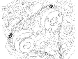
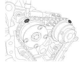
Set No.1 cylinder to TDC/compression.
| (1) |
Turn the crankshaft pulley clockwise and align its groove with the timing mark "T" of the lower timing chain cover. 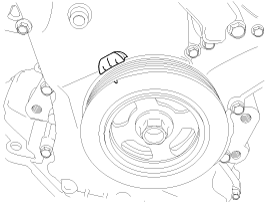
|
| (2) |
Check that the mark of the camshaft timing sprockets are in
straight line on the cylinder head surface as shown in the illustration.
If not, turn the crankshaft clockwise one revolution (360°). 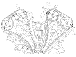
|
Do not rotate engine counterclockwise. |
|
|
| 3. |
Inspect the valve clearance.
| (1) |
With No.1 cylinder at TDC inspect clearances only on the valves shown in diagram below. 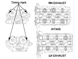
Measurement method.
| A. |
Using a thickness gauge, measure the clearance between the tappet and the base circle of camshaft. |
| B. |
Record the out-of-specification valve clearance measurements.
They will be used later to determine the required replacement adjusting
tappet. |
Valve clearance
Specification
Engine coolant temperature : 20°C [68°F]
Limit
Intake : 0.10 ~ 0.30mm (0.0039 ~ 0.0118in.)
Exhaust : 0.20 ~ 0.40mm (0.0078 ~ 0.0157in.)
|
|
| (2) |
Turn the crankshaft pulley clockwise one revolution (360°)
and align the groove with timing mark "T" of the lower timing chain
cover. |
| (3) |
With No.4 cylinder at TDC inspect clearances only the valves shown in diagram below. (Refer to procedure step 1.) 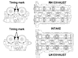
|
|
| 4. |
Adjust the intake and exhaust valve clearance.
| (1) |
Set the No.1 cylinder to the TDC/compression. |
| (2) |
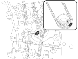
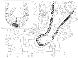
Remove the timing chain.
|
Before removing the timing chain, mark the RH/LH timing chain
with an identification based on the location of the sprocket because
the identification mark on the chain for TDC (Top Dead Center) can be
erased. |
|
| (3) |
Remove the fuel pump bracket (A). 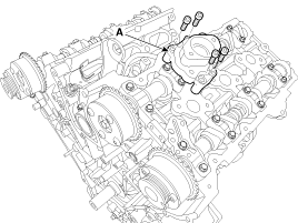
|
| (4) |
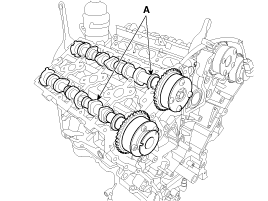
Remove the LH/RH camshaft bearing cap (A) and thrust bearing cap (B). 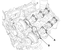
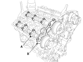
|
| (5) |
Remove the LH/RH camshaft assembly (A). 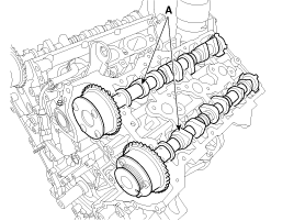
|
| (7) |
Measure the thickness of the removed tappet using a micrometer. 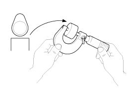
|
| (8) |
Calculate the thickness of a new tappet so that the valve clearance comes within the specified value.
T : Thickness of removed tappet
A : Measured valve clearance
N : Thickness of new tappet
Intake : N = T + [A - 0.20mm(0.0079in.)]
Exhaust : N = T + [A - 0.30mm (0.0118in.)]
|
|
| (9) |
Select a new tappet with a thickness as close as possible to the calculated value.
|
Shims are available in 41size increments of 0.015mm (0.0006in.) from 3.00mm (0.118in.) to 3.600mm (0.1417in.) |
|
| (10) |
Place a new tappet on the cylinder head.
|
Apply engine oil at the selected tappet on the side and top surface. |
|
| (11) |
Install the intake and exhaust camshaft. |
| (12) |
Install the bearing caps.
(Refer to Cylinder Head Assembly - "Camshaft") |
| (13) |
Install the timing chain.
(Refer to Timing System - "Timing Chain") |
| (14) |
Turn the crankshaft two turns in the operating direction
(clockwise) and realign crankshaft sprocket and camshaft sprocket timing
marks.
|
| (15) |
Recheck the valve clearance.
Valve clearance (Engine coolant temperature : 20°C [68°F])
[Specification]
Intake : 0.17 ~ 0.23mm (0.0067 ~ 0.0090in.)
Exhaust : 0.27 ~ 0.33mm (0.0106 ~ 0.0129in.)
|
|
|
Specifications
DescriptionSpecificationsLimitGeneralTypeV-type, DOHCNumber of cylinders6Bore92mm(3.6220in.)Stroke83.8mm(3.2992in.)Total displacement3,342cc(203.94cu.in.)Compression ratio11.5 : 1F ...
Troubleshooting
SymptomSuspect areaRemedyEngine misfire with abnormal internal lower engine noises.Worn crankshaft bearings.Loose or damaged engine drive plate.Replace the crankshaft and bearings ...
 Hyundai Azera: Repair procedures
Fifth generation HG (2011–2026) / Hyundai Azera 2011-2026 Service Manual / Engine Mechanical System / General Information / Repair procedures
Hyundai Azera: Repair procedures
Fifth generation HG (2011–2026) / Hyundai Azera 2011-2026 Service Manual / Engine Mechanical System / General Information / Repair procedures

 Specifications
 Troubleshooting