 Hyundai Azera: Sub Frame Repair procedures
Fifth generation HG (2011–2026) / Hyundai Azera 2011-2026 Service Manual / Suspension System / Front Suspension System / Sub Frame Repair procedures
Hyundai Azera: Sub Frame Repair procedures
Fifth generation HG (2011–2026) / Hyundai Azera 2011-2026 Service Manual / Suspension System / Front Suspension System / Sub Frame Repair procedures
Fifth generation HG (2011–2026) / Hyundai Azera 2011-2026 Service Manual / Suspension System / Front Suspension System / Sub Frame Repair procedures
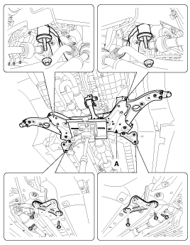
| Replacement |
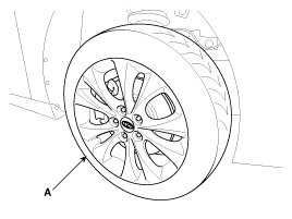
| 1. |
Remove the front wheel & tire (A).
|

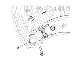
| 2. |
Loosen the bolt (A) and then disconnect the universal joint assembly from the pinion of the steering gear box.
|
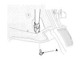
| 3. |
Remove the under cover (A).
|
| 4. |
Remove the sprit pin and castle nut and then disconnect the tie-rod end (A) from the front knuckle.
|
| 5. |
Loosen the bolt & nut and then remove the lower arm (A).
|
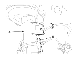
| 6. |
Disconnect the stabilizer link (B) with the front strut assembly (A) after loosening the nut.
|
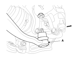
| 7. |
Loosen the bolt and then remove the front roll stopper (A).
|
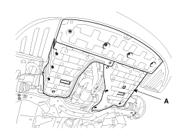
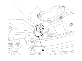
| 8. |
Disconnect the muffler rubber hanger (A).
|
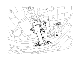
| 9. |
Loosen the bolts & nuts and then remove the sub frame (A).
|
| 10. |
Remove the front lower arm.
(Refer to Front Suspension System - "Front Lower Arm") |
| 11. |
Remove the front strut assembly.
(Refer to Front Suspension System - "Front Strut Assembly") |
| 12. |
Remove the front stabilizer bar.
(Refer to Front Suspension System - "Front Stabilizer Bar") |
| 13. |
Remove the steering gear box.
|
| 14. |
Installation is the reverse of removal. |
| 15. |
Check the alignment.
(Refer to Tires/Wheels - "Alingnent") |
 Front Stabilizer Bar Repair procedures
Replacement
1.
Remove the front wheel & tire (A).
Tightening torque:
88.3 ~ 107.9N.m (9.0 ~ 11.0kgf.m, 65.1 ~ 79.6lb-ft)
•
Be careful not to damage to the hub ...

See also:
Parking brake
...
Schematic Diagrams
Circuit Diagram
...
1. Crankcase emission control system
The positive crankcase ventilation system is employed to prevent air pollution
caused by blow-by gases being emitted from the crankcase.
This system supplies fresh filtered air to the crankcase thro ...
Categories
Hyundai Azera Manuals

© 2011-2026 Copyright www.hgmanual.com