 Hyundai Azera: Turn Signal Lamp Repair procedures
Fifth generation HG (2011–2024) / Hyundai Azera 2011-2024 Service Manual / Body Electrical System / Lighting System / Turn Signal Lamp Repair procedures
Hyundai Azera: Turn Signal Lamp Repair procedures
Fifth generation HG (2011–2024) / Hyundai Azera 2011-2024 Service Manual / Body Electrical System / Lighting System / Turn Signal Lamp Repair procedures
Fifth generation HG (2011–2024) / Hyundai Azera 2011-2024 Service Manual / Body Electrical System / Lighting System / Turn Signal Lamp Repair procedures
| Removal |
Door mirror turn signal lamp
| 1. |
Disconnect the negative (-) battey terminal. |
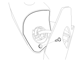
| 2. |
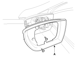
Remove the mirror (A).
|
| 3. |
Remove the outside mirror cover (A).
|
| 4. |
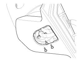
Remove the lower cover (A) of outside rear view mirror.
|
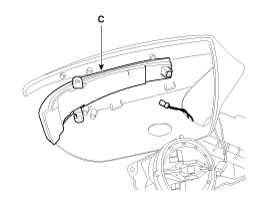
| 5. |
Detach the lower part from the upper part after loosening screws (4EA).
|
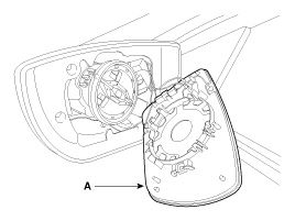
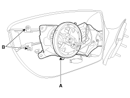
| 6. |
Remove the outside rear view mirror actuator (A) and 2 screws
(B). Disconnect the connector and remove the door mirror turn signal
lamp (C).
|
| 7. |
The installation is the reverse of removal. |
Puddle lamp
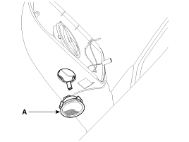
| 1. |
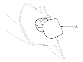
Remove the puddle lamp(A) under the outside rear mirror.
|
 Rear Combination Lamp Repair procedures
Rear Combination Lamp (Outside)
1.
Disconnect the negative (-) battery terminal.
2.
If the bulbs should be only replaced without removing lamp assembly, replace the turn signal lamp bulb (A).
...
 Trunk Lamps Repair procedures
Removal
1.
Disconnect the negative (-) battery terminal.
2.
Remove the luggage room lamp (B) when prying the clip (A) with a flat-up screwdriver.
3.
Remove the luggage room lamp bulb in ca ...
See also:
Components and Components Location
Component Location
Components
1. Heater Case (LH)2. Heater Case (RH)3. Separator4. Heater Case (Lower)5. Drain Hose6. Insulation7.Shower Duct (RH)8. Temp Actuator(PA)9. Temp Door Cam10. Evapora ...
Smart Cruise Control Unit Schematic Diagrams
Circuit Diagram
...
Inhibitor Switch Specifications
Specifications
? Type: Combination of output signals from 4 terminals
Power supply (V)12Output typeCombination of output signals
Signal Code Table
PP-RRR-NNN-DDSignal 112V12V00000Signal 20 ...
Categories
Hyundai Azera Manuals

© 2011-2024 Copyright www.hgmanual.com