 Hyundai Azera: Front Driveshaft Repair procedures
Fifth generation HG (2011Ц2024) / Hyundai Azera 2011-2024 Service Manual / Driveshaft and axle / Driveshaft Assembly / Front Driveshaft Repair procedures
| Replacement |
| 1. |
Loosen the wheel lug nuts slightly.
Raise the vehicle, and make sure it is securely supported. |
| 2. |
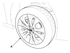
Remove the front wheel and tire (A) from front hub.
|
| 3. |
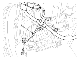
Loosen the wheel speed sensor mount bolt and then remove the wheel speed sensor (A) from knuckle.
|
| 4. |
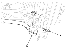
Remove the tie rod end ball joint (A) from the knuckle.
|
| 5. |
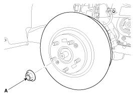
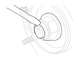
Remove driveshaft coking nut(A) from the front hub under applying the brake.
|
| 6. |
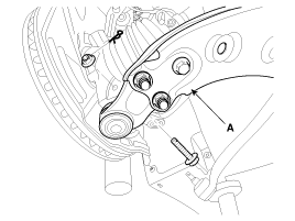
Remove the lower arm (A) from the knuckle.
|
| 7. |
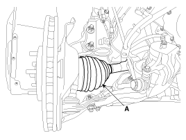
Disconnect the driveshaft (A) from the front hub assembly.
|
| 8. |
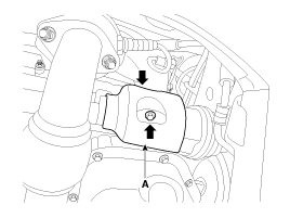
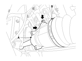
Remove the driveshaft cover (A).
|
| 9. |
Loosen the mounting bolts and then remove the inner shaft (A) & driveshaft assembly (B). [RH]
|
| 10. |
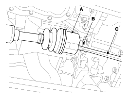
Removing the driveshaft (A) from the transaxle (B) by using a pry bar (C) as shown below. [LH]
|
| 11. |
Inatall in the reverse order of removal. |
| 12. |
Chek the alignment.
(Refer to Suspension System - "Alignment")
|
 Front Driveshaft Components and Components Location
Component Location
1. Driveshaft(LH)2. Inner shaft bearing bracket assembly3. Driveshaft(RH)
Components
1. BJ Assembly2. Clip3. BJ Boot Band4. BJ Boot5. Dynamic Damper Band6. Dynamic Damp ...
 TJ Joint Components and Components Location
Components
[LH]
1. BJ assembly2. Circlip3. BJ boot band4. BJ boot 5. Dynamic damper band6. Dynamic damper7. Shaft8. TJ boot band 9. TJ boot10. Spider assembly11. Snap ring12. TJ case 13. Circl ...
See also:
Cooling Fan Repair procedures
Removal and Installation
1.
Remove the battery and tray.
(Refer to Engine Electrical System - "Battery")
2.
Remove the air duct and air cleaner assembly.
(Refer to Intake And Exhaust System ...
A/V external amplifier Components and Components Location
Components
Pin No.Pin nameFunctionPower [W]A1Battery +power input10AA2Battery +power input10AA3Battery +power input10AA4-no connect?A5CAN +CAN +20mAA6CAN -CAN -20mAA7ACCACC/IGN input(on/off)10mAA ...
Yaw-rate and G Sensor Description and Operation
Description
When the vehicle is turning with respect to a vertical axis
the yaw rate sensor detects the yaw rate electroniclly by the vibration
change of plate fork inside the yaw rate sensor.
...

