 Hyundai Azera: Injector Drive Box (IDB) Schematic Diagrams
Fifth generation HG (2011–2024) / Hyundai Azera 2011-2024 Service Manual / Engine Control/Fuel System / Engine Control System / Injector Drive Box (IDB) Schematic Diagrams
Hyundai Azera: Injector Drive Box (IDB) Schematic Diagrams
Fifth generation HG (2011–2024) / Hyundai Azera 2011-2024 Service Manual / Engine Control/Fuel System / Engine Control System / Injector Drive Box (IDB) Schematic Diagrams
Fifth generation HG (2011–2024) / Hyundai Azera 2011-2024 Service Manual / Engine Control/Fuel System / Engine Control System / Injector Drive Box (IDB) Schematic Diagrams
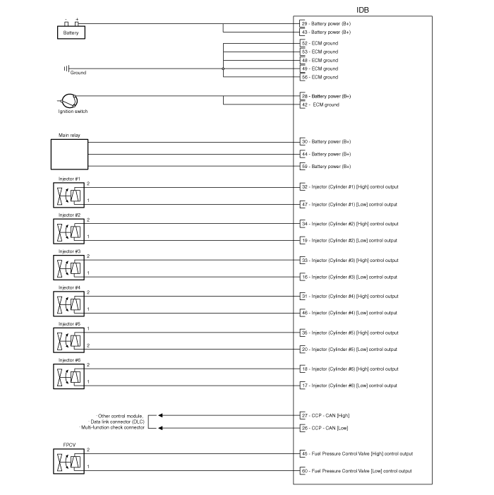
| IDB terminal and Inoutput |

| IDB terminal function |
Connector [CLG02]
| Pin No. | Description | Connected to |
| 1 | - | ? |
| 2 | - | ? |
| 3 | - | ? |
| 4 | - | ? |
| 5 | - | ? |
| 6 | - | ? |
| 7 | - | ? |
| 8 | - | ? |
| 9 | - | ? |
| 10 | - | ? |
| 11 | - | ? |
| 12 | - | ? |
| 13 | - | ? |
| 14 | - | ? |
| 15 | - | ? |
| 16 | Injector (Cylinder #3) [Low] control output | Injector (Cylinder #3) |
| 17 | Injector (Cylinder #6) [Low] control output | Injector (Cylinder #6) |
| 18 | Injector (Cylinder #6) [High] control output | Injector (Cylinder #6) |
| 19 | Injector (Cylinder #2) [Low] control output | Injector (Cylinder #2) |
| 20 | Injector (Cylinder #5) [Low] control output | Injector (Cylinder #5) |
| 21 | - | ? |
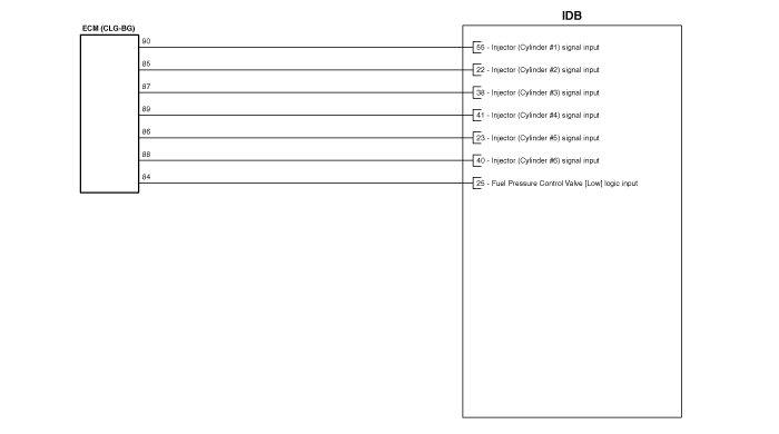
| 22 | Injector (Cylinder #2) signal input | Engine Control Module (ECM) |
| 23 | Injector (Cylinder #5) signal input | Engine Control Module (ECM) |
| 24 | - | ? |
| 25 | Fuel Pressure Control Valve (FPRV) logic input | Engine Control Module (ECM) |
| 26 | CCP-CAN [Low] | Other control module, Data Link Connector (DLC), Multi-purpose check connector |
| 27 | CCP-CAN [High] | Other control module, Data Link Connector (DLC), Multi-purpose check connector |
| 28 | Battery power (B+) | Ignition switch |
| 29 | Battery power (B+) | Main relay |
| 30 | Battery power (B+) | Main relay |
| 31 | Injector (Cylinder #4) [High] control output | Injector (Cylinder #4) |
| 32 | Injector (Cylinder #1) [High] control output | Injector (Cylinder #1) |
| 33 | Injector (Cylinder #3) [High] control output | Injector (Cylinder #3) |
| 34 | Injector (Cylinder #2) [High] control output | Injector (Cylinder #2) |
| 35 | Injector (Cylinder #5) [High] control output | Injector (Cylinder #5) |
| 36 | - | ? |
| 37 | - | ? |
| 38 | Injector (Cylinder #3) signal input | Engine Control Module (ECM) |
| 39 | - | ? |
| 40 | Injector (Cylinder #6) signal input | Engine Control Module (ECM) |
| 41 | Injector (Cylinder #4) signal input | Engine Control Module (ECM) |
| 42 | Battery power (B+) | Ignition switch |
| 43 | Battery power (B+) | Main relay |
| 44 | Battery power (B+) | Main relay |
| 45 | Fuel Pressure Control Valve (FPRV) [High] control output | Fuel Pressure Control Valve (FPRV) |
| 46 | Injector (Cylinder #4) [Low] control output | Injector (Cylinder #4) |
| 47 | Injector (Cylinder #1) [Low] control output | Injector (Cylinder #1) |
| 48 | ECM ground | Chassis ground |
| 49 | ECM ground | Chassis ground |
| 50 | ECM ground | Chassis ground |
| 51 | - | ? |
| 52 | ECM ground | Chassis ground |
| 53 | ECM ground | Chassis ground |
| 54 | - | ? |
| 55 | Injector (Cylinder #1) signal input | Engine Control Module (ECM) |
| 56 | - | ? |
| 57 | - | ? |
| 58 | - | ? |
| 59 | Battery power (B+) | Main relay |
| 60 | Fuel Pressure Control Valve (FPRV) [Low] control output | Fuel Pressure Control Valve (FPRV) |
| IDB Terminal input/output signal |
Connector [CLG02]
| Pin No. | Description | Condition | Type | Level |
| 1 | - | ? | ? | ? |
| 2 | - | ? | ? | ? |
| 3 | - | ? | ? | ? |
| 4 | - | ? | ? | ? |
| 5 | - | ? | ? | ? |
| 6 | - | ? | ? | ? |
| 7 | - | ? | ? | ? |
| 8 | - | ? | ? | ? |
| 9 | - | ? | ? | ? |
| 10 | - | ? | ? | ? |
| 11 | - | ? | ? | ? |
| 12 | - | ? | ? | ? |
| 13 | - | ? | ? | ? |
| 14 | - | ? | ? | ? |
| 15 | - | ? | ? | ? |
| 16 | Injector (Cylinder #3) [Low] control output | Idle | Pulse | High: Battery voltage |
| Relay ON | Low: Max. 1.0V | |||
| 17 | Injector (Cylinder #6) [Low] control output | Idle | Pulse | High: Battery voltage |
| Relay ON | Low: Max. 1.0V | |||
| 18 | Injector (Cylinder #6) [High] control output | Idle | Pulse | High: Battery voltage ~ 80V |
| Relay ON | Low: Battery voltage | |||
| 19 | Injector (Cylinder #2) [Low] control output | Idle | Pulse | High: Battery voltage |
| Relay ON | Low: Max. 1.0V | |||
| 20 | Injector (Cylinder #5) [Low] control output | Idle | Pulse | High: Battery voltage |
| Relay ON | Low: Max. 1.0V | |||
| 21 | - | ? | ? | ? |
| 22 | Injector (Cylinder #2) signal input | Idle | Pulse | High: Battery voltage |
| Low: Max. 1.0V | ||||
| 23 | Injector (Cylinder #5) signal input | Idle | Pulse | High: Battery voltage |
| Low: Max. 1.0V | ||||
| 24 | - | ? | ? | ? |
| 25 | Fuel Pressure Control Valve (FPRV) logic input | ? | ? | ? |
| ? | ? | ? | ||
| 26 | CCP-CAN [Low] | Recessive | Pulse | 2.0 ~ 3.0V |
| Dominant | 2.75 ~ 4.5V | |||
| 27 | CCP-CAN [High] | Recessive | Pulse | 2.0 ~ 3.0V |
| Dominant | 2.75 ~ 4.5V | |||
| 28 | Battery power (B+) | IG OFF | DC voltage | Max. 0.5V |
| IG ON | Battery voltage | |||
| 29 | Battery power (B+) | IG OFF | DC voltage | Max. 0.5V |
| IG ON | Battery voltage | |||
| 30 | Battery power (B+) | IG OFF | DC voltage | Max. 0.5V |
| IG ON | Battery voltage | |||
| 31 | Injector (Cylinder #4) [High] control output | Idle | Pulse | High: Battery voltage ~ 80V |
| Relay ON | Low: Battery voltage | |||
| 32 | Injector (Cylinder #1) [High] control output | Idle | Pulse | High: Battery voltage ~ 80V |
| Relay ON | Low: Battery voltage | |||
| 33 | Injector (Cylinder #3) [High] control output | Idle | Pulse | High: Battery voltage ~ 80V |
| Relay ON | Low: Battery voltage | |||
| 34 | Injector (Cylinder #2) [High] control output | Idle | Pulse | High: Battery voltage ~ 80V |
| Relay ON | Low: Battery voltage | |||
| 35 | Injector (Cylinder #5) [High] control output | Idle | Pulse | High: Battery voltage ~ 80V |
| Relay ON | Low: Battery voltage | |||
| 36 | - | ? | ? | ? |
| 37 | - | ? | ? | ? |
| 38 | Injector (Cylinder #3) signal input | Idle | Pulse | High: Battery voltage |
| Low: Max. 1.0V | ||||
| 39 | - | ? | ? | ? |
| 40 | Injector (Cylinder #6) signal input | Idle | Pulse | High: Battery voltage |
| Low: Max. 1.0V | ||||
| 41 | Injector (Cylinder #4) signal input | Idle | Pulse | High: Battery voltage |
| Low: Max. 1.0V | ||||
| 42 | Battery power (B+) | IG OFF | DC voltage | Max. 0.5V |
| IG ON | Battery voltage | |||
| 43 | Battery power (B+) | IG OFF | DC voltage | Max. 0.5V |
| IG ON | Battery voltage | |||
| 44 | Battery power (B+) | IG OFF | DC voltage | Max. 0.5V |
| IG ON | Battery voltage | |||
| 45 | Fuel Pressure Control Valve (FPRV) [High] control output | Idle | DC voltage | Battery voltage |
| Max. 1.0V | ||||
| 46 | Injector (Cylinder #4) [Low] control output | Idle | Pulse | High: Battery voltage |
| Relay ON | Low: Max. 1.0V | |||
| 47 | Injector (Cylinder #1) [Low] control output | Idle | Pulse | High: Battery voltage |
| Relay ON | Low: Max. 1.0V | |||
| 48 | ECM ground | Idle | DC voltage | Max. 50mV |
| 49 | ECM ground | Idle | DC voltage | Max. 50mV |
| 50 | ECM ground | Idle | DC voltage | Max. 50mV |
| 51 | - | ? | ? | ? |
| 52 | ECM ground | Idle | DC voltage | Max. 50mV |
| 53 | ECM ground | Idle | DC voltage | Max. 50mV |
| 54 | - | ? | ? | ? |
| 55 | Injector (Cylinder #1) signal input | Idle | Pulse | High: Battery voltage |
| Low: Max. 1.0V | ||||
| 56 | - | ? | ? | ? |
| 57 | - | ? | ? | ? |
| 58 | - | ? | ? | ? |
| 59 | Battery power (B+) | IG OFF | DC voltage | Max. 0.5V |
| IG ON | Battery voltage | |||
| 60 | Fuel Pressure Control Valve (FPRV) [Low] control output | Idle | DC voltage | Battery voltage |
| Max. 1.0V |
| Circuit Diagram |
 Engine Control Module (ECM) Repair procedures
Removal
When replacing the ECM, the vehicle equipped with the immobilizer must be performed procedure as below.
[In the case of installing used ECM]
1.
Perform "ECM Neutr ...
 Injector Drive Box (IDB) Repair procedures
Removal
1.
Turn the ignition switch off and disconnect the battery negative (-) cable.
2.
Disconnect the injector drive box (IDB) connector (A).
3.
Remove the air cleaner assembly.
(Refer ...
See also:
Closing the fuel filler lid
1. To install the cap, turn it clockwise until it clicks one time. This indicates
that the cap is securely tightened.
2. Close the fuel filler lid and push it lightly and make sure that it is secure ...
Head Lamps Repair procedures
Inspection
1.
Check-points upon head lamp failure (HID)
(1)
Check the battery voltage. (Low beam will be on when the battery voltage above 9V.)
(2)
Check the fuse and relay.
(3)
Check th ...
Engine Control Module (ECM) Schematic Diagrams
ECM Terminal And Input/Output signal
ECM Terminal Function
Connector [ELG-A]
Pin No.DescriptionConnected to1-?2-?3-?4Immobilizer Lamp control outputImmobilizer Lamp [Without Button Engine Sta ...
Categories
Hyundai Azera Manuals

© 2011-2024 Copyright www.hgmanual.com