
 Hyundai Azera: Rear Glass Defogger Printed Heater Repair procedures
Fifth generation HG (2011–2026) / Hyundai Azera 2011-2026 Service Manual / Body Electrical System / Rear Glass Defogger / Rear Glass Defogger Printed Heater Repair procedures
Hyundai Azera: Rear Glass Defogger Printed Heater Repair procedures
Fifth generation HG (2011–2026) / Hyundai Azera 2011-2026 Service Manual / Body Electrical System / Rear Glass Defogger / Rear Glass Defogger Printed Heater Repair procedures
Fifth generation HG (2011–2026) / Hyundai Azera 2011-2026 Service Manual / Body Electrical System / Rear Glass Defogger / Rear Glass Defogger Printed Heater Repair procedures
| Inspection |
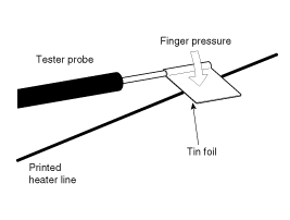
Wrap tin foil around the end of the voltmeter test lead to
prevent damaging the heater line. Apply finger pressure on the tin foil,
moving the tin foil along the grid line to check for open circuits. |

| 1. |
Turn on the defogger switch and use a voltmeter to measure
the voltage of each heater line at the glass center point. If a voltage
of approximately 6V is indicated by the voltmeter, the heater line of
the rear window is considered satisfactory.
|

| 2. |
If a heater line is burned out between the center point and (+) terminal, the voltmeter will indicate 12V.
|

| 3. |
If a heater line is burned out between the center point and (-) terminal, the voltmeter will indicate 0V.
|

| 4. |
To check for open circuits, slowly move the test lead in the
direction that the open circuit seems to exist. Try to find a point
where a voltage is generated or changes to 0V. The point where the
voltage has changed is the open-circuit point.
|

| 5. |
Use an ohmmeter to measure the resistance of each heater line
between a terminal and the center of a grid line, and between the same
terminal and the center of one adjacent heater line. The section with a
broken heater line will have a resistance twice as that in other
sections. In the affected section, move the test lead to a position
where the resistance sharply changes.
|

Repair Of Broken Heater Line
Prepare the following items:
| 1. |
Conductive paint. |
| 2. |
Paint thinner. |
| 3. |
Masking tape. |
| 4. |
Silicone remover. |
| 5. |
Using a thin brush:
Wipe the glass adjacent to the broken heater line, clean with
silicone remover and attach the masking tape as shown. Shake the
conductive paint container well, and apply three coats with a brush at
intervals of about 15 minutes apart. Remove the tape and allow
sufficient time for drying before applying power. For a better finish,
scrape away excess deposits with a knife after the paint has completely
dried. (Allow 24 hours).
|

 Components and Components Location
Component Location
1. Rear glass defogger relay (Engine room relay box)2. Rear glass defogger switch (A/C controller)3. Rear glass defogger
...
 Rear Glass Defogger Switch Repair procedures
Inspection
1.
The rear glass defogger switch inputs can be checked using the GDS.
2.
To check the input value of rear glass defogger switch, select option "IPM".
3.
To consult the present ...
See also:
Headlight (Headlamp) welcome function
When the headlight is in the ON or AUTO position and all doors (and trunk) are
closed and locked, if you press the door unlock button on the smart key, the headlights
(and/or parking light) will com ...
Components and Components Location
Components
1. Windshield glass2. Windshield glass upper molding3. Windshield glass side molding4. Windshield glass side mounting bracket
...
Vapor hose and fuel filler cap
The vapor hose and fuel filler cap should be inspected at those intervals specified
in the maintenance schedule. Make sure that a new vapor hose or fuel filler cap
is correctly replaced. ...
Categories
Hyundai Azera Manuals

© 2011-2026 Copyright www.hgmanual.com