 Hyundai Azera: TJ Joint Repair procedures
Fifth generation HG (2011–2024) / Hyundai Azera 2011-2024 Service Manual / Driveshaft and axle / Driveshaft Assembly / TJ Joint Repair procedures
Fifth generation HG (2011–2024) / Hyundai Azera 2011-2024 Service Manual / Driveshaft and axle / Driveshaft Assembly / TJ Joint Repair procedures
| Replacement |
|
| 1. |
Remove the Front Driveshaft.
(Refer to Driveshaft Assembly - “Front Driveshaft”) |
| 2. |
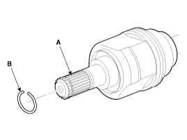
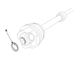
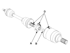
Remove the circlip (B) from the driveshaft spline (A).
|
| 3. |
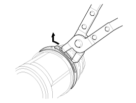
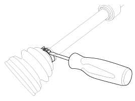
Remove both boot bands from the TJ case.
|
| 4. |
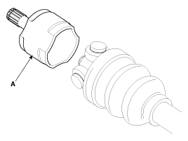
Remove the TJ case (A).
|
| 5. |
Remove the snap ring (A) from the shaft.
|
| 6. |
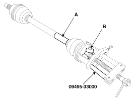
Remove the spider assembly (B) from the driveshaft (A) using the special tool (09495-33000).
|
| 7. |
Clean the spider assembly. |
| 8. |
Remove the TJ boot (A).
|
| Inspection |
| 1. |
Check the spider assembly for roller rotation, wear or corrosion. |
| 2. |
Check the groove inside the joint case for wear or corrosion |
| 3. |
Check the TJ boots for damage and deterioration. |
| Installation |
| 1. |
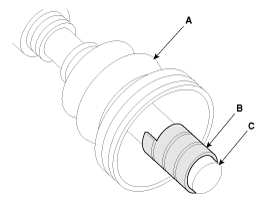
Wrap tape around the driveshaft spline(TJ) to prevent damage to the boot. |
| 2. |
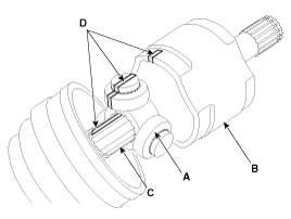
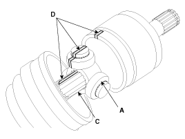
Using the alignment marks (D) made during disassembly as a
guide, install the spider assembly (A) and snap ring (B) on the
driveshaft splines (C).
|
| 3. |
Add specified grease to the joint boot as much as it was wiped away at inspection. |
| 4. |
Install the both boot band. |
| 5. |
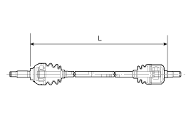
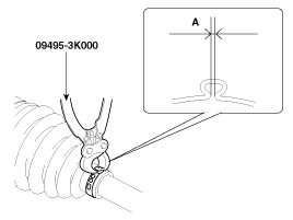
To control the air in the TJ boot, keep the specified distance between the boot bands when they are tightened.
| |||||||||
| 6. |
Using the SST(09495-3K000), secure the TJ boot bands.
|
| 7. |
Install the Front Driveshaft.
(Refer to Driveshaft Assembly - “Front Driveshaft”) |
 TJ Joint Components and Components Location
Components
[LH]
1. BJ assembly2. Circlip3. BJ boot band4. BJ boot 5. Dynamic damper band6. Dynamic damper7. Shaft8. TJ boot band 9. TJ boot10. Spider assembly11. Snap ring12. TJ case 13. Circl ...
 Dynamic Damper Components and Components Location
Components
1. BJ assembly2. Circlip3. BJ boot band4. BJ boot 5. Dynamic damper band6. Dynamic damper7. Shaft8. TJ boot band 9. TJ boot10. Spider assembly11. Snap ring12. TJ case 13. Circlip
...
See also:
Tire terminology and definitions
Air Pressure:
The amount of air inside the tire pressing outward on the tire. Air pressure
is expressed in pounds per square inch (psi) or kilopascal (kPa).
Accessory Weight:
This means the comb ...
CVVT Oil Temperature Sensor (OTS) Description and Operation
Description
Continuous Variable Valve Timing (CVVT) system advances or
retards the valve timing of the intake and exhaust valve in accordance
with the ECM control signal which is calculated by ...
Good driving practices
Never move the shift lever from P (Park) or N (Neutral) to any other position
with the accelerator pedal depressed.
Never move the shift lever into P (Park) when the vehicle is in motion.
Be ...
Categories
Hyundai Azera Manuals
© 2011-2024 Copyright www.hgmanual.com


