
 Hyundai Azera: Description and Operation
Fifth generation HG (2011–2026) / Hyundai Azera 2011-2026 Service Manual / Body Electrical System / Multifunction switch / Description and Operation
Hyundai Azera: Description and Operation
Fifth generation HG (2011–2026) / Hyundai Azera 2011-2026 Service Manual / Body Electrical System / Multifunction switch / Description and Operation
Fifth generation HG (2011–2026) / Hyundai Azera 2011-2026 Service Manual / Body Electrical System / Multifunction switch / Description and Operation
| Description |
| Communication network diagram |
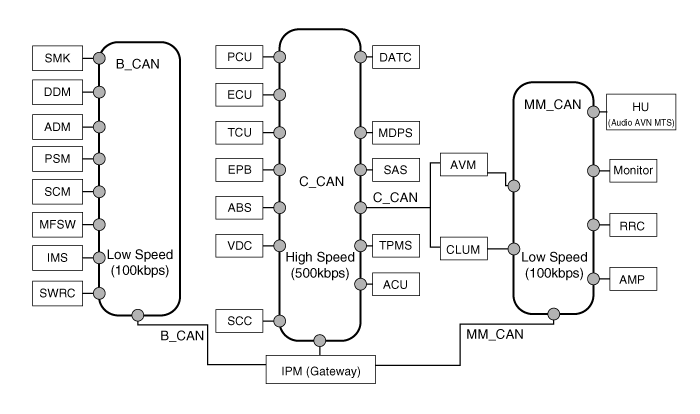
| Abbreviation | Explanation |
| C_CAN | Chassis Controller Area Network |
| B_CAN | Body Controller Area Network |
| MM_CAN | Multi media Controller Area Network |
| SMK | Smart Key ECU |
| DDM | Driver Door Module |
| ADM | Assist Door Module |
| PSM | Power Seat Module |
| SCM | Steering Column Module |
| IMS | Integrated Memory System |
| MFSW | Multi-Function Switch |
| SWRC | Steering Wheel Remote Controller |
| PCU | Power-train Control Unit |
| ECU | Engine Control Unit |
| TCU | Transmission Control Unit |
| EPB | Electronic Parking Brake |
| ABS | Anti-lock Brake System |
| VDC | Vechile Stability Control |
| SCC | Smart Cruise Control |
| DATC | Dual Automatic Temp Control |
| MDPS | Motor Driven Power Steering |
| SAS | Steering Angle Sensor |
| TPMS | Tire Pressure Monitoring System |
| ACU | Airbag Control Unit |
| AVM | Around View Monitor |
| CLUM | Cluster Module |
| HU | Head Unit |
| RRC | Rear Remote Control |
| IPM | Intelligent itegrated Platform Module |
 Components and Components Location
Component (1)
1. Steering column2. Lighting switch3. Wiper switch4. Screw5. Clock spring
Component (2)
...
 Repair procedures
Inspection (With GDS)
1.
Check BCM input/output specification of multifunction switch
using the GDS. If the specification is abnormal, replace the lamp or
wiper switch.
2.
If diagnosis is ...
See also:
Valve Body Components and Components Location
Components Location
1. PCV adjust screw2. Solenoid valve3. Oil temperature sensor4. Accumulator5. Low & reverse brake(LR/B) pressure flow hole6. Under drive brake (UD/B) pressure flow hole
...
Catalytic Converter Repair procedures
Removal
[Catalytic Converter (WCC)]
1.
Remove the exhaust manifold.
(Refer to Engine Mechanical System - "Exhaust Manifold")
[Catalytic Converter (UCC)]
1.
Remove the Center Muffler.
...
Turn by Turn
The Turn by Turn feature can be used through Blue Link®.
(1) Direction Indicator Image
(2) Remaining distance until next point
(3) The Count bar is divided into a total of 9 levels.
(4) Next ...
Categories
Hyundai Azera Manuals

© 2011-2026 Copyright www.hgmanual.com