PODS-F ECU
| 1. |
Disconnect the battery negative cable, and wait for at least three minutes before beginning work. |
| 2. |
Remove the front passenger seat assembly.
|
| 3. |
Disconnect the PODS-F ECU connector. |
| 4. |
Remove the PODS-F ECU.
|
PODS-F Mat
| 1. |
Disconnect the battery negative cable, and wait for at least three minutes before beginning work. |
| 2. |
Remove the front passenger seat assembly.
|
| 3. |
Disconnect the PODS-F ECU connector. |
| 4. |
Remove the front seat cushion assembly.
|
PODS-F ECU
| 1. |
Install the PODS-F ECU on the Front seat track assembly. |
| 2. |
Connect the PODS-F ECU connector. |
| 3. |
Install the front passenger seat assembly.
|
| 4. |
Reconnect the battery negative cable. |
| 5. |
After installing the PODS-F, confirm proper system operation :
| A. |
Turn the ignition switch ON the SRS indicator should be turned on for about six seconds and then go off. |
| B. |
Telltale lamp will turn on for 4 seconds and be turned off
for 3 seconds. After the 7 seconds, it shall remain off if the PODS-F
does not require suppression and the passenger airbag is enabled. |
|
Be sure to perform PODS-F reset with GDS after replacing PODS-F equipped seat cushion.
|
|
PODS-F Mat
| 1. |
Install the PODS-F Mat equipped seat cushion assembly on the front seat assembly.
|
| 2. |
Connect the PODS-F mat connector. |
| 3. |
Install the front passenger seat assembly.
|
| 4. |
Reconnect the battery negative cable. |
| 5. |
After installing the PODS-F, confirm proper system operation :
| A. |
Turn the ignition switch ON the SRS indicator should be turned on for about six seconds and then go off. |
| B. |
Telltale lamp will turn on for 4 seconds and be turned off
for 3 seconds. After the 7 seconds, it shall remain off if the PODS-F
does not require suppression and the passenger airbag is enabled. |
|
Be sure to perform PODS-F zeroing with GDS after replacing PODS-F equipped seat cushion.
|
|
You should perform PODS-F reset procedure after service or
replacement about all part of the passenger seat. (Not included full
seat assembly)
| 1. |
Ignition “OFF�, connect GDS. |
| 2. |
Ignition “ON� & Engine “OFF�, select Airbag system and “PODS-F Reset� mode. 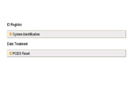
|
| 3. |
The GDS will show the two PODS-F Zeroing function steps.
| (1) |
Erase PODS-F diagnostic codes. |
| (2) |
PODS-F initialization. 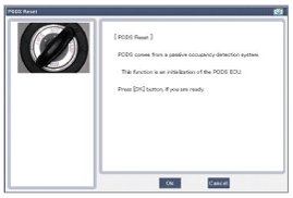
|
This step must be done PODS-F reset, when the front passenger seat is empty. |
|
|
| 4. |
Select product configuration.
| (1) |
No Heater Seat configuration: (C1) |
| (2) |
Heater Seat Configuration: (C2) |
| (3) |
Vent & Heater Seat Configuration: (C3) 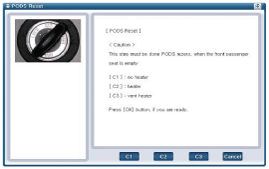
|
|
Before the starting the PODS-F zeroing process, cross check seat correct configuration with actual vehicle.
If you see the center console, you can find different buttons
per each different seat configuration type. (Refer to the below
picture)
| 1. |
No Heater Seat Configuration : (C1) 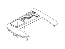
|
| 2. |
Heater Seat Configuration : (C2) 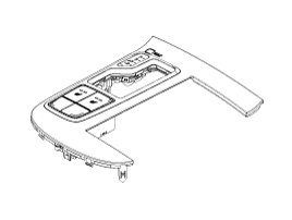
|
| 3. |
Vent & Heater Seat Configuration: (C3) 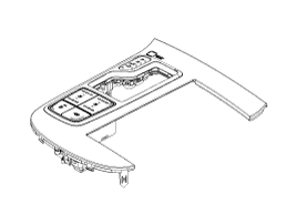
|
|
|
| 5. |
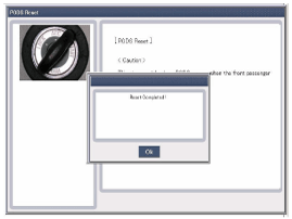
The PODS-F initialization procedure will be performed. 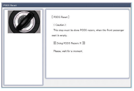
|
Erase the SRSCM diagnostic codes after completing the PODS-F zeroing. |
|
In case of zeroing failure
| - |
Code 01 : Requestor ID out of range. |
| - |
Code 02 : ODS ECU faults. |
| - |
Code 03 : ODS sensor short to ground. |
| - |
Code 04 : Open between ODS ECU and mat. |
| - |
Code 05 : ODS ECU has not been trimmed. |
| - |
Code 06 : Configuration disabled in ECU calibration. |
| - |
Code 07 : Configuration value out of range. (Calibratable) |
| - |
Code 08 : Used in zero Request response only. |
| - |
Code 09 : Algo enabled this ignition cycles. |
| - |
Code 10 : QX Frequency not stable. |
| - |
Code 0A : Upper offset value created during the zero process. |
| - |
Code 0B : Lower offset value created during the zero process. |
| - |
Code 0C : Voltage diagnostic |
| - |
Code 0D : The delta of QX_Freq_Low and QX_Freq_High must remain low. |
| - |
Code 0E : Temperature is above O deg C during the zero process. |
| - |
Code 0F : Re-read QX Final compare delta limit. (Zero verify) |
|
|
Circuit Diagram (1)
Circuit Diagram (2)
Circuit Diagram (3)
SRSCM Connector terminal
Pin Function (Connector A)Pin Function (Connector B)1Ignition1Seat belt pretensioner [Driver] Hig ...
See also:
Rear Stabilizer Bar Repair procedures
Replacement
1.
Remove the rear wheel & tire (A).
Tightening torque:
88.3 ~ 107.9N.m (9.0 ~ 11.0kgf.m, 65.1 ~ 79.6lb-ft)
•
Be careful not to damage to the hub ...
Oil Pressure Switch Components and Components Location
Components
1. Oil cover2. Oil cover gasket3. Oil pressure switch
...
(if equipped)
The system has been equipped with a rear view camera for user safety by
allowing a wider rear range of vision.
The rear view camera will automatically operate when the ENGINE START/STOP
butto ...

 Hyundai Azera: Passive Occupant Detection System (PODS-F) Repair procedures
Fifth generation HG (2011–2026) / Hyundai Azera 2011-2026 Service Manual / Restraint / SRSCM / Passive Occupant Detection System (PODS-F) Repair procedures
Hyundai Azera: Passive Occupant Detection System (PODS-F) Repair procedures
Fifth generation HG (2011–2026) / Hyundai Azera 2011-2026 Service Manual / Restraint / SRSCM / Passive Occupant Detection System (PODS-F) Repair procedures


 Schematic Diagrams