 Hyundai Azera: Fuel Filter Repair procedures
Fifth generation HG (2011–2026) / Hyundai Azera 2011-2026 Service Manual / Engine Control/Fuel System / Fuel Delivery System / Fuel Filter Repair procedures
Hyundai Azera: Fuel Filter Repair procedures
Fifth generation HG (2011–2026) / Hyundai Azera 2011-2026 Service Manual / Engine Control/Fuel System / Fuel Delivery System / Fuel Filter Repair procedures
Fifth generation HG (2011–2026) / Hyundai Azera 2011-2026 Service Manual / Engine Control/Fuel System / Fuel Delivery System / Fuel Filter Repair procedures
| Removal |
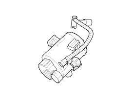
| 1. |
Remove the fuel pump.
(Refer to Fuel Delivery System - “Fuel Pump”) |
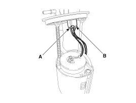
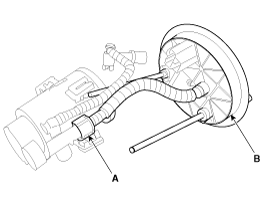
| 2. |
Disconnect the electric pump wiring connector (A) and the fuel sender connector (B).
|
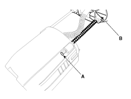
| 3. |
Remove the cushion pipe fixing clip (A), and then separate the head assembly (B) from reservoir cup.
|
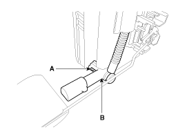
| 4. |
Remove the return nozzle (B) after releasing the fixing hook (A).
|
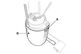
| 5. |
Remove the reservoir-cup (B) after releasing the fixing hooks (A).
|
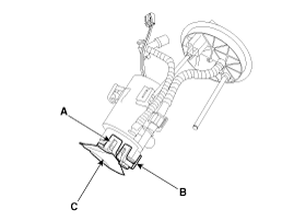
| 6. |
Remove the pre-filter (C) after releasing the fixing hooks (A,B).
|

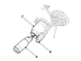
| 7. |
Separate the electric pump motor (A) and regulator (B) from the fuel filter (C).
|
| 8. |
Disconnect the connector (A), and then remove the head assembly (B).
|
| Installation |
| 1. |
Installation is reserve of removal. |
 Fuel Pump Repair procedures
Inspection
[Fuel pump]
1.
Turn the ignition switch OFF, and then remove battery (-) cable.
2.
Remove the fuel pump assembly.
3.
Check motor operation by fuel pump connector (A) connecti ...
 Fuel Pump Motor Repair procedures
Removal
1.
Remove the fuel pump.
(Refer to Fuel Delivery System - “Fuel Pump”)
2.
Disconnect the electric pump wiring connector (A) and the fuel sender connector (B).
3.
Remove the c ...
See also:
Components and Components Location
Components
1. Main crash pad assembly2. Side speaker grille [LH]3. Center speaker grille4. Side speaker grille [RH]5. Alarm speaker assembly6. Center speaker assembly7. Photo sensor 8. Crash pad ...
Steering Gear box Repair procedures
Replacement
1.
Remove the front wheel & tire (A).
Tightening torque :
88.3 ~ 107.9N.m (9.0 ~ 11.0kgf.m, 65.1 ~ 79.6lb-ft)
•
Be careful not to damage to the h ...
Components and Components Location
Components Location
1. PCV Valve2. Canister3. Purge Control Solenoid Valve (PCSV)4. Fuel Tank Pressure Sensor (FTPS)5. Canister Close Valve (CCV)6. Fuel Level Sensor (FLS)7. Fuel Tank Air Filt ...
Categories
Hyundai Azera Manuals

© 2011-2026 Copyright www.hgmanual.com