
 Hyundai Azera: TJ Joint Repair procedures
Fifth generation HG (2011–2026) / Hyundai Azera 2011-2026 Service Manual / Driveshaft and axle / Driveshaft Assembly / TJ Joint Repair procedures
Hyundai Azera: TJ Joint Repair procedures
Fifth generation HG (2011–2026) / Hyundai Azera 2011-2026 Service Manual / Driveshaft and axle / Driveshaft Assembly / TJ Joint Repair procedures
Fifth generation HG (2011–2026) / Hyundai Azera 2011-2026 Service Manual / Driveshaft and axle / Driveshaft Assembly / TJ Joint Repair procedures
| Replacement |
|

| 1. |
Remove the Front Driveshaft.
(Refer to Driveshaft Assembly - “Front Driveshaft�) |
| 2. |
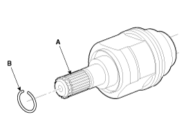
Remove the circlip (B) from the driveshaft spline (A).
|
| 3. |
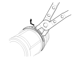
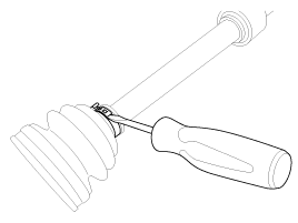
Remove both boot bands from the TJ case.
|
| 4. |
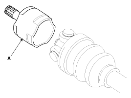
Remove the TJ case (A).
|
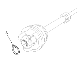
| 5. |
Remove the snap ring (A) from the shaft.
|
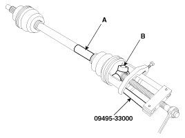
| 6. |
Remove the spider assembly (B) from the driveshaft (A) using the special tool (09495-33000).
|
| 7. |
Clean the spider assembly. |
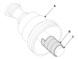
| 8. |
Remove the TJ boot (A).
|
| Inspection |
| 1. |
Check the spider assembly for roller rotation, wear or corrosion. |
| 2. |
Check the groove inside the joint case for wear or corrosion |
| 3. |
Check the TJ boots for damage and deterioration. |
| Installation |
| 1. |
Wrap tape around the driveshaft spline(TJ) to prevent damage to the boot. |
| 2. |
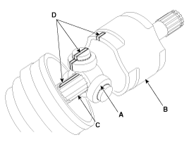
Using the alignment marks (D) made during disassembly as a
guide, install the spider assembly (A) and snap ring (B) on the
driveshaft splines (C).
|
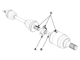
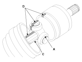
| 3. |
Add specified grease to the joint boot as much as it was wiped away at inspection. |
| 4. |
Install the both boot band. |
| 5. |
To control the air in the TJ boot, keep the specified distance between the boot bands when they are tightened.
| |||||||||
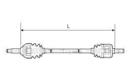
| 6. |
Using the SST(09495-3K000), secure the TJ boot bands.
|
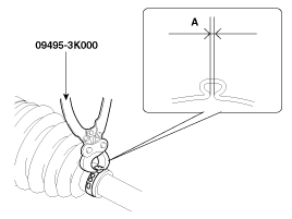
| 7. |
Install the Front Driveshaft.
(Refer to Driveshaft Assembly - “Front Driveshaft�) |
 TJ Joint Components and Components Location
Components
[LH]
1. BJ assembly2. Circlip3. BJ boot band4. BJ boot 5. Dynamic damper band6. Dynamic damper7. Shaft8. TJ boot band 9. TJ boot10. Spider assembly11. Snap ring12. TJ case 13. Circl ...
 Dynamic Damper Components and Components Location
Components
1. BJ assembly2. Circlip3. BJ boot band4. BJ boot 5. Dynamic damper band6. Dynamic damper7. Shaft8. TJ boot band 9. TJ boot10. Spider assembly11. Snap ring12. TJ case 13. Circlip
...
See also:
Deleting a Device
Press the key
Select [Phone]
Select [Paired Phone List]
From the paired phone list, select the device you want to delete and select the
button.
✽ NOTICE
When deleting the current ...
Manifold Absolute Pressure Sensor (MAPS) Schematic Diagrams
Circuit Diagram
...
Navigation system
The navigation system ascertains the present position of your vehicle by using
information from satellites and guides you to the place you assign as the destination.
Detailed information for the nav ...
Categories
Hyundai Azera Manuals

© 2011-2026 Copyright www.hgmanual.com