 Hyundai Azera: Repair procedures
| Inspection |
Front Door Lock Actuator Inspection
| 1. |
Remove the front door trim.
|
| 2. |
Remove the front door module. |
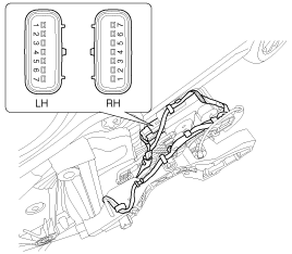
| 3. |
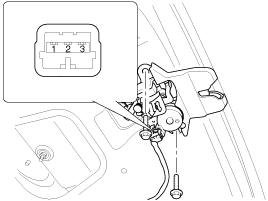
Disconnect the 7P connector from the actuator.
|
| 4. |
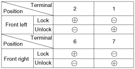
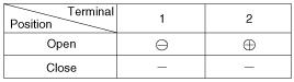
Check actuator operation by connecting power and ground
according to the table. To prevent damage to the actuator, apply battery
voltage only momentarily.
|
Rear Door Lock Actuator Inspection
| 1. |
Remove the rear door trim.
|
| 2. |
Remove the rear door module. |
| 3. |
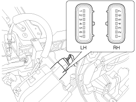
Disconnect the 7P connector from the actuator.
|
| 4. |
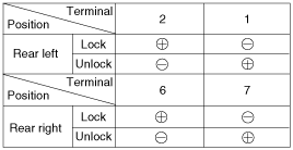
Check actuator operation by connecting power and ground
according to the table. To prevent damage to the actuator, apply battery
voltage only momentarily.
|
Trunk Lid Release Actuator Inspection
| 1. |
Remove the trunk lid trim panel.
|
| 2. |
Disconnect the 3P connector from the actuator.
|
| 3. |
Check actuator operation by connecting power and ground
according to the table. To prevent damage to the actuator, apply battery
voltage only momentarily.
|
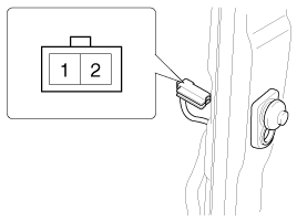
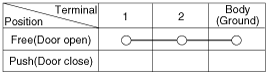
Front Door Lock Switch Inspection
| 1. |
Remove the front door trim panel.
|
| 2. |
Remove the front door module. |
| 3. |
Disconnect the 6P connector from the actuator.
|
| 4. |
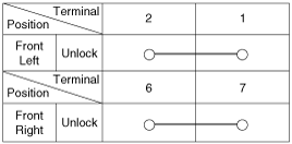
Check for continuity between the terminals in each switch position when inserting the key into the door according to the table.
|
Rear Door Lock Switch Inspection
| 1. |
Remove the rear door trim panel.
|
| 2. |
Remove the rear door module. |
| 3. |
Disconnect the 7P connector from the actuator.
|
| 4. |
Check for continuity between the terminals in each switch position according to the table.
|

Trunk Lid Open Switch Inspection
| 1. |
Remove the trunk lid trim.
|
| 2. |
Disconnect the 3P connector from the actuator.
|
| 3. |
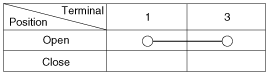
Check for continuity between the terminals in each switch position according to the table.
|
Door Switch Inspection
Remove the door switch and check for continuity between the terminals.
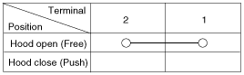
Hood Switch Inspection
| 1. |
Disconnect the connector from the hood switch (A).
|
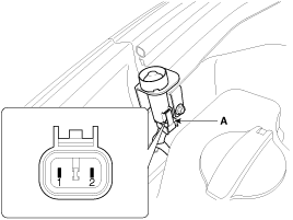
| 2. |
Check for continuity between the terminals and ground according to the table.
|
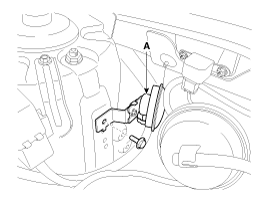
Burglar Horn Inspection
| 1. |
Remove the burglar horn (A) after removing 1 bolt and disconnect the 2P connector from the burglar horn.
|
| 2. |
Test the burglar horn by connecting battery power to the terminal 1 and ground the terminal 2. |
| 3. |
The burglar horn should make a sound. If the burglar horn fails to make a sound replace it. |
 Description and Operation
Description
Remote Keyless Entry System
The described function is a radio-frequency remote control
for central doors locking / unlocking, trunk release and Panic activity
of an automotive vehi ...
 Transmitter Specifications
Specification
ItemDescriptionPower source3VOperating temperature-20°C ~ +60°CRF ModulationFSKRF frequency433.92MHzBattery1EA (CR2032)
An inappropriately disposed battery ...
See also:
Maintenance service
You should exercise the utmost care to prevent damage to your vehicle and injury
to yourself whenever performing any maintenance or inspection procedures.
Should you have any doubts concerning the i ...
General Information
The Micro 570 Analyzer (Canada only)
The Micro 570 Analyzer provides the ability to test the
charging and starting systems, including the battery, starter and
alternator.
...
Theft-alarm stage
The alarm will be activated if any of the following occurs while the system is
armed.
A door is opened without using the smart key.
A door is opened without using the mechanical key.
The trun ...
Categories
Hyundai Azera Manuals

© 2011-2026 Copyright www.hgmanual.com