 Hyundai Azera: Body Control Module (BCM) Repair procedures
Fifth generation HG (2011–2026) / Hyundai Azera 2011-2026 Service Manual / Body Electrical System / BCM (Body Control Module) / Body Control Module (BCM) Repair procedures
Hyundai Azera: Body Control Module (BCM) Repair procedures
Fifth generation HG (2011–2026) / Hyundai Azera 2011-2026 Service Manual / Body Electrical System / BCM (Body Control Module) / Body Control Module (BCM) Repair procedures
Fifth generation HG (2011–2026) / Hyundai Azera 2011-2026 Service Manual / Body Electrical System / BCM (Body Control Module) / Body Control Module (BCM) Repair procedures
| Removal |
| 1. |
Disconnect the negative (-) battery terminal. |
| 2. |
Remove the crash pad lower panel.
|
| 3. |
Remove the Reinforcing panel after loosening the mounting bolt and nut.
|
| 4. |
Disconnect the IPM connectors, loosening the nuts (4EA).
|
| 5. |
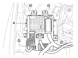
Disconnect the rear connector, and then remove the IPM. |
| Installation |
| 1. |
Install the IPM. |
| 2. |
Install the reinforcing panel. |
| 3. |
Install the crash pad lower panel. |
| 4. |
Disconnect the negative (-) battery terminal. |
| IPM Diagnosis With GDS |
| 1. |
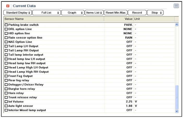
It will be able to diagnose defects of IPM with GDS quickly.
GDS can operates actuator forcefully, input/output value monitoring and
self diagnosis. |
| 2. |
Select model and "IPM". |
| 3. |
Select the module to check. |
| 4. |
Select "Input/output monitoring", if you will check current
data of body network system. It provides input/output status of each
module.
|
| 5. |
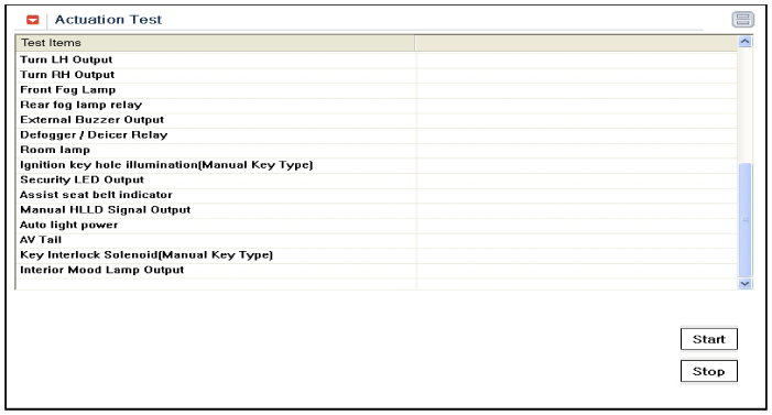
If you will check each module data operation forcefully, select "Actuation test".
|
| 6. |
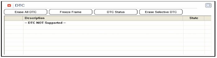
To check the DTC of the each module, select "DIAGNOSTIC TROUBLE CODES".
|
| 7. |
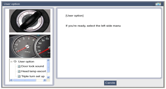
If you want to change user option, select “user option”.
|
 Body Control Module (BCM) Description and Operation
Description
Communication network diagram
AbbreviationExplanationC_CANChassis Controller Area NetworkB_CANBody Controller Area NetworkMM_CANMulti media Controller Area NetworkSMKSmart Key ECUDDM ...

See also:
Automatic turn off function (if equipped)
The interior lights automatically turn off approximately 20 minutes after the
ignition switch is turned off.
With the theft alarm system, the interior lights automatically turns off approximately
5 ...
ICM (Integrated Circuit Module) Relay Box Repair procedures
Inspection
Two Turn Unlock Relay
Check for continuity between the terminals.
1.
There should be continuity between the No.18 and No.17
terminals when power and ground are connected to the No. ...
Pre-tensioner seat belt
Your vehicle is equipped with driver's and front passenger's pre-tensioner seat
belts. The purpose of the pretensioner is to make sure that the seat belts fit tightly
against the occupan ...
Categories
Hyundai Azera Manuals

� 2011-2026 Copyright www.hgmanual.com