 Hyundai Azera: Ignition Coil Repair procedures
Fifth generation HG (2011–2026) / Hyundai Azera 2011-2026 Service Manual / Engine Electrical System / Ignition System / Ignition Coil Repair procedures
Hyundai Azera: Ignition Coil Repair procedures
Fifth generation HG (2011–2026) / Hyundai Azera 2011-2026 Service Manual / Engine Electrical System / Ignition System / Ignition Coil Repair procedures
Fifth generation HG (2011–2026) / Hyundai Azera 2011-2026 Service Manual / Engine Electrical System / Ignition System / Ignition Coil Repair procedures
| Removal and Installation |
| [LH] |
| 1. |
Disconnect the battery nagative terminal. |
| 2. |
Remove the engine cover. |
| 3. |
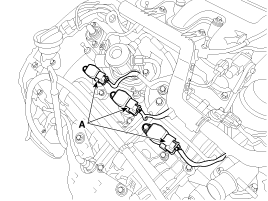
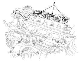
Disconnect the LH ignition coil connectors (A) and then remove the LH ignition coils.
|

| 4. |
Installation is reverse order of removal. |
| [RH] |
| 1. |
Disconnect the battery nagative terminal. |
| 2. |
Remove the surge tank.
|
| 3. |
Disconnect the RH ignition coil connectors (A) and then remove the RH ignition coils.
|
| 4. |
Installation is reverse order of removal. |
| Inspection |
| 1. |
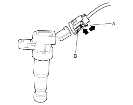
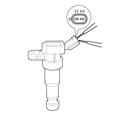
Measure the primary coil resistance between terminals (+) and (-).
|
 Ignition Coil Components and Components Location
Components
1. Condensor2. Bracket3. Ignition coil4. Ignition coil harness
...
 Spark Plug Components and Components Location
Components
1. Spark plug
...
See also:
Passive Occupant Detection System (PODS-F) Components and Components Location
Components
...
Water pump Troubleshooting
Troubleshooting
SymptomsPossible CausesRemedyCoolant leakage
•
From the bleed hole of the water pump
Visually check
•
Check leaks after about ten-minute warming up.
•
If cool ...
Vehicle break-in process
No special break-in period is needed. By following a few simple precautions for
the first 600 miles (1,000 km) you may add to the performance, economy and life
of your vehicle.
Do not race the e ...
Categories
Hyundai Azera Manuals

© 2011-2026 Copyright www.hgmanual.com