
 Hyundai Azera: IMS Power Seat Control Schematic Diagrams
Fifth generation HG (2011–2026) / Hyundai Azera 2011-2026 Service Manual / Body Electrical System / IMS (Integrated Memory) / IMS Power Seat Control Schematic Diagrams
Hyundai Azera: IMS Power Seat Control Schematic Diagrams
Fifth generation HG (2011–2026) / Hyundai Azera 2011-2026 Service Manual / Body Electrical System / IMS (Integrated Memory) / IMS Power Seat Control Schematic Diagrams
Fifth generation HG (2011–2026) / Hyundai Azera 2011-2026 Service Manual / Body Electrical System / IMS (Integrated Memory) / IMS Power Seat Control Schematic Diagrams
| Circuit diagram |
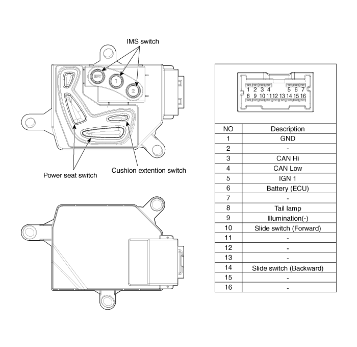
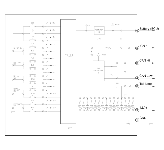
 IMS (Integrated Memory System) module Repair procedures
Removal
1.
Remove the negative (-) battery terminal.
2.
Remove the driver seat in the car.
(Refer to Body - "Front Seat Assembly")
3.
Remove the IMS module (A) after loosening 3 screws in ...
 IMS Power Seat Control Repair procedures
Inspection
1.
It will be able to diagnose defects of IMS with GDS quickly.
GDS can operates actuator forcefully, input/output value monitoring and
self diagnosis.
2.
Select model and "IPM ...
See also:
Blue Link®
Hyundai aims to offer differentiated customer values through a ‘Connected Car
Life,’ which is to provide consumers with fast and reliable IT technology. As consumers’
lifestyles become more an ...
Driving at night
Because night driving presents more hazards than driving in the daylight, here
are some important tips to remember:
Slow down and keep more distance between you and other vehicles, as it may
...
Before starting
Close and lock all doors.
Position the seat so that all controls are easily reached.
Adjust the inside and outside rearview mirrors.
Be sure that all lights work.
Check all gauges.
Check ...
Categories
Hyundai Azera Manuals

© 2011-2026 Copyright www.hgmanual.com