 Hyundai Azera: Side Impact Sensor (SIS) Repair procedures
Fifth generation HG (2011–2026) / Hyundai Azera 2011-2026 Service Manual / Restraint / SRSCM / Side Impact Sensor (SIS) Repair procedures
Hyundai Azera: Side Impact Sensor (SIS) Repair procedures
Fifth generation HG (2011–2026) / Hyundai Azera 2011-2026 Service Manual / Restraint / SRSCM / Side Impact Sensor (SIS) Repair procedures
Fifth generation HG (2011–2026) / Hyundai Azera 2011-2026 Service Manual / Restraint / SRSCM / Side Impact Sensor (SIS) Repair procedures
| Removal |
Front Side Impact Sensor
| 1. |
Disconnect the battery negative cable and wait for at least three minutes before beginning work. |
| 2. |
Remove the door scuff trim.
|
| 3. |
Remove the center pillar trim.
|
| 4. |
Disconnect the side impact sensor connector (B).
|
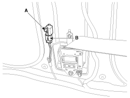
| 5. |
Loosen the side impact sensor mounting bolt (A) and remove the side impact sensor. |
Rear Side Impact Sensor
| 1. |
Disconnect the battery negative cable and wait for at least three minutes before beginning work. |
| 2. |
Remove the rear seat back assembly.
|
| 3. |
Disconnect the rear side impact sensor connector (B).
|
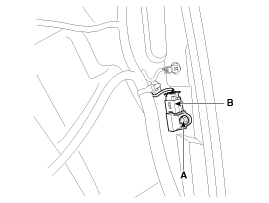
| 4. |
Loosen the rear side impact sensor mounting bolt and then remove the rear side impact sensor (A). |
Pressure Side Impact Sensor
|

| 1. |
Disconnect the battery negative cable, and wait for at least three minutes before beginning work. |
| 2. |
Remove the front door trim.
|
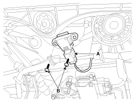
| 3. |
Disconnect the pressure side impact sensor connector (A) and remove the pressure side impact sensor mounting screws (B).
|
| Installation |
Front Side Impact Sensor
|
| 1. |
Install the new side impact sensor with the bolt and then connect the side impact sensor connector.
|
| 2. |
Install the center pillar trim.
|
| 3. |
Install the door scuff trim.
|
| 4. |
Reconnect the battery negative cable. |
| 5. |
After installing the Side Impact Sensor, confirm proper system operation:
|
Rear Side Impact Sensor
|
| 1. |
Install the new rear side impact sensor with a bolt and then connect the rear side impact sensor connector.
|
| 2. |
Install the rear seat.
|
| 3. |
Reconnect the battery negative cable. |
| 4. |
After installing the Side Impact Sensor, confirm proper system operation:
|
Pressure Side Impact Sensor
| 1. |
Install the new pressure side impact sensor with the screws (B) then connect the pressure side impact sensor connector (A).
|
| 2. |
Install the front door trim.
|
| 3. |
Reconnect the battery negative cable. |
| 4. |
After installing the pressure side impact sensor, confirm proper system operation:
|
 Side Impact Sensor (SIS) Components and Components Location
Components
...
 Seat Belt Buckle Switch (BS) Description and Operation
Description
The SRSCM shall monitor the status of the driver and front
passenger seat belt buckle. The SRSCM provides one pin each for the
driver and front passenger seat belt buckle status inp ...
See also:
Repair procedures
Adjustment
1.
After loosening the hinge (A) mounting bolt, adjust the hood (B) by moving it up or down, or right or left.
2.
Adjust the hood height by turning the hood overslam bumpers (C).
...
SS-B Solenoid Valve(ON/OFF) Specifications
Specifications
ON/OFF Solenoid Valve(SS-A, SS-B)
? Control type : Normal low type
Control pressure [kpa (kgf/cm?, psi)]490.33(5.0, 71.12) Internal resistance(?)10~11
...
Description and Operation
Description
Communication network diagram
AbbreviationExplanationC_CANChassis Controller Area NetworkB_CANBody Controller Area NetworkMM_CANMulti media Controller Area NetworkSMKSmart Key ECUDDM ...
Categories
Hyundai Azera Manuals

© 2011-2026 Copyright www.hgmanual.com