 Hyundai Azera: Camshaft Repair procedures
Fifth generation HG (2011–2026) / Hyundai Azera 2011-2026 Service Manual / Engine Mechanical System / Cylinder Head Assembly / Camshaft Repair procedures
Hyundai Azera: Camshaft Repair procedures
Fifth generation HG (2011–2026) / Hyundai Azera 2011-2026 Service Manual / Engine Mechanical System / Cylinder Head Assembly / Camshaft Repair procedures
Fifth generation HG (2011–2026) / Hyundai Azera 2011-2026 Service Manual / Engine Mechanical System / Cylinder Head Assembly / Camshaft Repair procedures
| Removal |
| [RH] |
| 1. |
Remove the RH bank timing chain.
(Refer to Timing System - "Timing Chain") |
| 2. |
Remove the RH exhaust CVVT oil control valve.
|
| 3. |
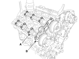
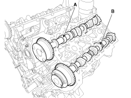
Remove the RH camshaft bearing cap (A) and thrust bearing cap (B).
|
| 4. |
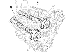
Remove the RH intake camshaft (A) and exhaust camshaft (B)
|
| [LH] |
| 1. |
Remove the RH/LH timing chain.
(Refer to Timing System - "Timing Chain") |
| 2. |
Remove the LH exhaust CVVT oil control valve.
|
| 3. |
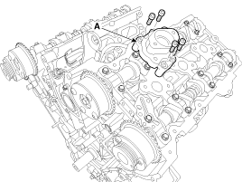
Remove the fuel pump bracket (A)
|
| 4. |
Remove the LH camshaft bearing cap (A) and thrust bearing cap (B).
|
| 5. |
Remove the LH intake camshaft (A) and exhaust camshaft (B)
|
| Installation |
|

| [RH] |
| 1. |
Install the RH intake camshaft (A) and exhaust camshaft (B)
RH Inkate camshaft
As for camshaft identification, refer to the table below.
RH Exhaust camshaft
As for camshaft identification, refer to the table below.
| ||||||||||||||||||||||
| 2. |
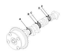
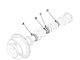
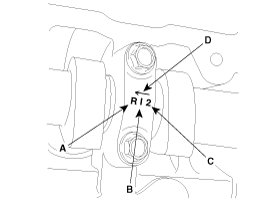
Install the bearing cap (A) and thrust bearing cap (B) with specified torque.
A : L(LH),R(RH)
B : I(Intake), None(Exhaust)
C : Journal number
D : Front mark
|

| 3. |
Install the other parts reverse order of removal. |
| [LH] |
| 1. |
Install the LH intake camshaft (A) and exhaust camshaft (B)
LH Inkate camshaft
As for camshaft identification, refer to the table below.
LH Exhaust camshaft
As for camshaft identification, refer to the table below.
| ||||||||||||||||||||||||||
| 2. |
Install the bearing cap (A) and thrust bearing cap (B) with specified torque.
A : L(LH),R(RH)
B : I(Intake), None(Exhaust)
C : Journal number
D : Front mark
|
| 3. |
Install the fuel pump bracket (A)
|
| 4. |
Install the other parts reverse order of removal. |
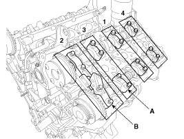
 Camshaft Components and Components Location
Components
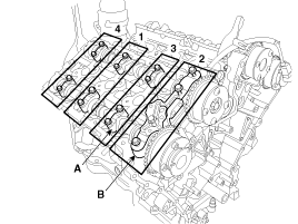
1. RH exhaust camshaft2. RH intake camshaft3. LH intake camshaft4. LH exhaust camshaft
...
 Cylinder Head Components and Components Location
Components
1. RH Cylinder head2. RH Cylinder head gasket3. LH Cylinder head4. LH Cylinder head gasket5. Cylinder block
1. Camshaft bearing cap 2. Camshaft thrust bearing cap 3. RH Exhaust ca ...
See also:
Alternator Repair procedures
Removal and Installation
1.
Disconnect the battery negative terminal.
2.
Remove the engine cover.
3.
Disconnect the alternator connector (A) and the cable (B) from the 'B' terminal.
4 ...
Drive Plate Repair procedures
Removal and Installation
1.
Remove the automatic transaxle.
(Refer to Automatic Transaxle System - "Automatic Transaxle")
2.
Remove the adapter plate (B) and the drive plate (A).
Tighteni ...
Blower Unit Components and Components Location
Component Location
Components
1. Duct Seal2. Duct Case3. Inlet Door4. Intake Actuator5. Inlet Duct Case (A)6. Climate control air filter7. Cluster Ionizer8. Climate control air filter Cover9. Bl ...
Categories
Hyundai Azera Manuals

© 2011-2026 Copyright www.hgmanual.com