 Hyundai Azera: CVVT Oil Control Valve (OCV) Repair procedures
Fifth generation HG (2011–2026) / Hyundai Azera 2011-2026 Service Manual / Engine Control/Fuel System / Engine Control System / CVVT Oil Control Valve (OCV) Repair procedures
Hyundai Azera: CVVT Oil Control Valve (OCV) Repair procedures
Fifth generation HG (2011–2026) / Hyundai Azera 2011-2026 Service Manual / Engine Control/Fuel System / Engine Control System / CVVT Oil Control Valve (OCV) Repair procedures
| Inspection |
| 1. |
Turn the ignition switch OFF. |
| 2. |
Disconnect the OCV connector. |
| 3. |
Measure resistance between the OCV terminals 1 and 2. |
| 4. |
Check that the resistance is within the specification.
|
| Removal |
| [CVVT Oil Control Valve (Intake)] |
| 1. |
Turn the ignition switch OFF and disconnect the battery negative (-) cable. |
| 2. |
Remove the intake manifold.
|
| 3. |
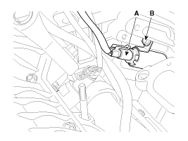
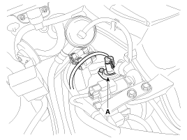
Disconnect the CVVT oil control valve connector (A). |
| 4. |
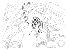
Remove the installation bolt (B), and then remove the valve from the engine.
[Bank 1]
[Bank 2]
|
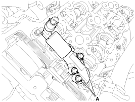
| [CVVT Oil Control Valve (Exhaust)] |
| 1. |
Turn the ignition switch OFF and disconnect the battery negative (-) cable. |
| 2. |
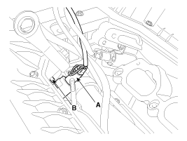
Disconnect the CVVT oil control valve connector (A).
[Bank 1]
[Bank 2]
|
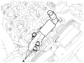
| 3. |
Remove the cylinder head cover.
|
| 4. |
Remove the installation bolt (A), and then remove the valve from the engine.
[Bank 1]
[Bank 2]
|
| Inatallation |
|

|
|
| Items | Component Side | Harness Side |
| Bank 1 (RH) | Grey | |
| Bank 2 (LH) | Black | |
| 1. |
Installation is reverse of removal.
|
 CVVT Oil Control Valve (OCV) Schematic Diagrams
Circuit Diagram
...
 Variable Intake Solenoid (VIS) Valve Description and Operation
Description
Variable Intake manifold Solenoid (VIS) valves are installed
on the intake manifold (VIS Valve 1) and the surge tank (VIS Valve 2).
These VIS valve 1 and 2 control vacuum modulators ...
See also:
Rail Pressure Sensor (RPS) Description and Operation
Description
Rail Pressure Sensor (RPS) is installed on the delivery pipe
and measures the instantaneous fuel pressure in the delivery pipe. The
sensing element (Semiconductor element) built in ...
Engine Coolant Temperature Sensor (ECTS) Repair procedures
Inspection
1.
Turn the ignition switch OFF.
2.
Disconnect the ECTS connector.
3.
Remove the ECTS (Refer to "Removal").
4.
After immersing the thermistor of the sensor into engine coola ...
Components and Components Location
Components
1. Hands free call switch2. Mic3. Front left speaker4. Front right speaker5. Audio head unit (hands free control)
? There is no hands free jack. This system supports Bluetooth(wir ...
Categories
Hyundai Azera Manuals
