 Hyundai Azera: Engine And Transmission Assembly Repair procedures
Fifth generation HG (2011–2026) / Hyundai Azera 2011-2026 Service Manual / Engine Mechanical System / Engine And Transmission Assembly / Engine And Transmission Assembly Repair procedures
Hyundai Azera: Engine And Transmission Assembly Repair procedures
Fifth generation HG (2011–2026) / Hyundai Azera 2011-2026 Service Manual / Engine Mechanical System / Engine And Transmission Assembly / Engine And Transmission Assembly Repair procedures
Fifth generation HG (2011–2026) / Hyundai Azera 2011-2026 Service Manual / Engine Mechanical System / Engine And Transmission Assembly / Engine And Transmission Assembly Repair procedures
| Removal |
|

|

| 1. |
Release the residual pressure in fuel line.
|
| 2. |
Remove the battery and battery tray.
|
| 3. |
Remove the engine cover. |
| 4. |
Remove the air duct and air cleaner assembly.
(Refer to Intake And Exhaust System - "Air Cleaner") |
| 5. |
Remove the engine room under cover. |
| 6. |
Drain the engine coolant.
(Refer to Cooling System - "Coolant") |
| 7. |
Remove the radiator upper hose and lower hose.
(Refer to Cooling System - "Radiator Hose") |
| 8. |
Recover the refrigerant and then remove the high pressure pipe and low pressure pipe.
|
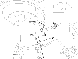
| 9. |
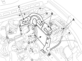
Disconnect the (+) cable (A) from the junction box. |
| 10. |
Remove the ECM.
|
| 11. |
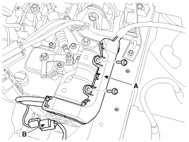
Disconnect the front connector (B), and then remove the wiring protector (A).
|
| 12. |
Remove the engine wirings from the engine room.
|
| 13. |
Remove the transaxle wire harness connectors and control cable from the transaxle.
|
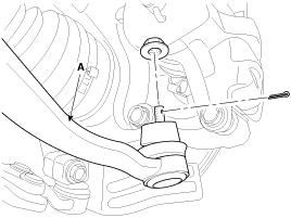
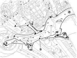
| 14. |
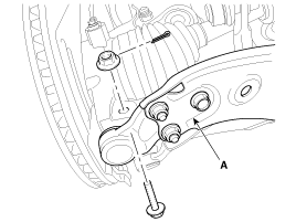
Loosen the bolt & nut and then disconnect the lower arm (A) from the front knuckle.
|
| 15. |
Remove the front stabilizer bar links (A).
|
| 16. |
Disconnect the tie-rod end (A) from the front knuckle.
|
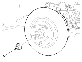
| 17. |
Remove the drive shaft coking nut (A) from the front hub.
|
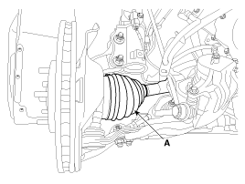
| 18. |
Disconnect the driveshaft (A) from the front hub assembly.
|
| 19. |
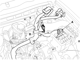
Loosen the bolt and then disconnect the universal joint assembly (A) from the pinion of the steering gear box.
|
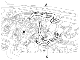
| 20. |
Disconnect the heater hoses.
(Refer to Cooling System - "Heater Hose") |
| 21. |
Disconnect the brake booster vacuum hose (A), the PSCV hose (B). Disconnect the and the fuel line (C).
|
| 22. |
Remove the front muffler.
(Refer to Intake And Exhaust System - "Front Muffler") |
| 23. |
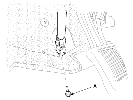
Remove the roll road bracket (A).
|
| 24. |
Rremove the sub frame (B).
|
| 25. |
Disconnect the ground cable, and then remove the engine mounting bracket.
(Refer to Engine And Transmission Assembly - "Engine Mounting") |
| 26. |
Disconnect the ground cable, and then remove the transaxle mounting bracket through bolt.
|
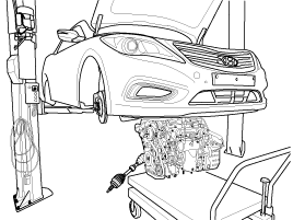
| 27. |
Remove the engine and transaxle assembly by lifting vehicle.
|
| Installation |
Installation is in the reverse order of removal.
Perform the following :
| • |
Adjust a shift cable. |
| • |
Refill engine with engine oil. |
| • |
Refill a transaxle with fluid. |
| • |
Refill a radiator and a reservoir tank with engine coolant. |
| • |
Place a heater control knob on "HOT" position. |
| • |
Clean battery posts and cable terminals and assemble. |
| • |
Inspect for fuel leakage. |
| - |
After assemble the fuel line, turn on the ignition switch (do
not operate the starter) so that the fuel pump runs for approximately
two seconds and fuel line pressurizes. |
| - |
Repeat this operation two or three times, then check for fuel leakage at any point in the fuel line. |
| • |
Bleed air from the cooling system. |
| - |
Start engine and let it run until it warms up. (until the radiator fan operates 3 or 4 times.) |
| - |
Turn Off the engine and let it cool down. Check the level in
the radiator, add coolant if needed. This will allow trapped air to be
removed from the cooling system. |
| - |
Put radiator cap on tightly, then run the engine again and check for leaks. |
 Engine Mounting Repair procedures
Removal and Installation
[Engine mounting support bracket]
1.
Install the jack to the edge of upper oil pan (A) to support the engine.
Insert the rubber block between jac ...
 Engine Hanger Components and Components Location
Components Location
...
See also:
Accelerator Position Sensor (APS) Specifications
Specification
AcceleratorPositionOutput Voltage (V)APS1APS2C.T0.7 ~ 0.80.29 ~ 0.46W.O.T3.85 ~ 4.351.93 ~ 2.18
...
Trunk Lid Weatherstrip Repair procedures
Replacement
1.
Remove the trunk lid weatherstrip (A).
•
Do not apply sealant to the body.
2.
Installation is the reverse of removal.
†...
Basic Mode Screen
(1) Mode Displays currently operating mode.
(2) Operation State From Repeat / Shuffle / Scan, displays the currently operating
function.
(3) File Index Displays the current file number.
(4) Fi ...
Categories
Hyundai Azera Manuals

© 2011-2026 Copyright www.hgmanual.com