
 Hyundai Azera: Compressor Repair procedures
Fifth generation HG (2011–2026) / Hyundai Azera 2011-2026 Service Manual / Heating,Ventilation, Air Conditioning / Air Conditioning System / Compressor Repair procedures
Hyundai Azera: Compressor Repair procedures
Fifth generation HG (2011–2026) / Hyundai Azera 2011-2026 Service Manual / Heating,Ventilation, Air Conditioning / Air Conditioning System / Compressor Repair procedures
Fifth generation HG (2011–2026) / Hyundai Azera 2011-2026 Service Manual / Heating,Ventilation, Air Conditioning / Air Conditioning System / Compressor Repair procedures
| Removal |
| 1. |
If the compressor is marginally operable, run the engine at
idle speed, and let the air conditioning work for a few minutes, then
shut the engine off. |
| 2. |
Disconnect the negative cable from the battery. |
| 3. |
Recover the refrigerant with a recovery/charging station. |
| 4. |
Loosen the drive belt.
|
| 5. |
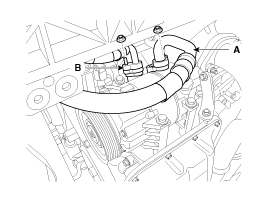
Remove the nuts, then disconnect the suction line (A) and discharge line (B) from the compressor.
Plug or cap the lines immediately after disconnecting them to avoid moisture and dust contamination.
|
| 6. |
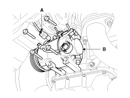
Disconnect the compressor clutch connector (A), and then remove 4 mounting bolts and the compressor (B).
|
| Installation |
| 1. |
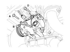
Make sure of the length of compressor mounting bolts, and then tighten it A>B>C>D order.
|
| 2. |
Install in the reverse order of removal, and note these items
|
| Inspection |
| 1. |
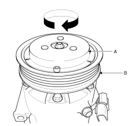
Check the plated parts of the limiter assembly (A) for color
changes, peeling or other damage. If there is damage, replace the
limiter assembly. |
| 2. |
Check the pulley (B) bearing play and drag by rotating the
pulley by hand. Replace the limiter assembly with a new one if it is
noisy or has excessive play/drag.
|
| External Control Valve Compressor Inspection (GDS) |
Compressor type: Fixed type compressor, External control valve, Internal control valve.
In cases of fixed type and internal control valve, it is possible to inspect compressor's operation with clutch noise.
When it comes to External control valve, however, it cannot be checked in this way bacause it doesn't have a clutch.
So, ECV should be inspected with GDS as below.
| 1. |
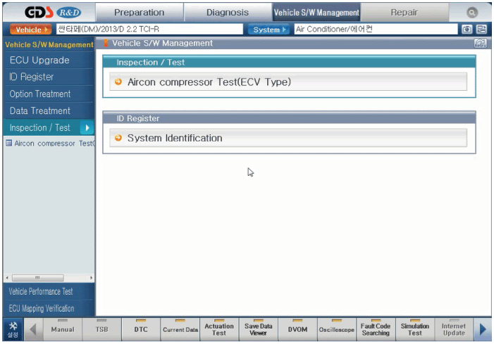
Connect GDS to the vehicle and select 'Aircon Compressor Test(ECV type)'
[ECV1]
|
| 2. |
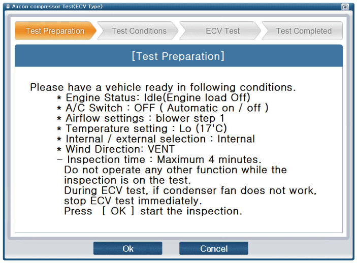
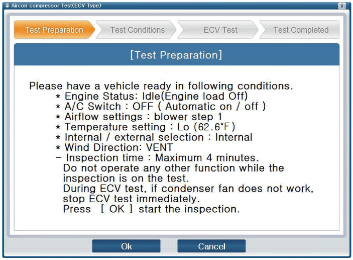
Make the vehicle ready as the GDS instruction on the monitor. (Turn off A/C 'switch' only)
[ECV2]
[ECV3]
|
| 3. |
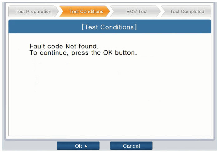
Check if other DTC codes are found before inspect ECV
compressor. If so, solve that problems first. If not, press 'OK' button
to continue.
[ECV4]
|

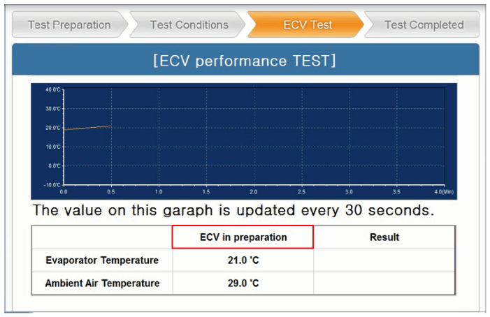
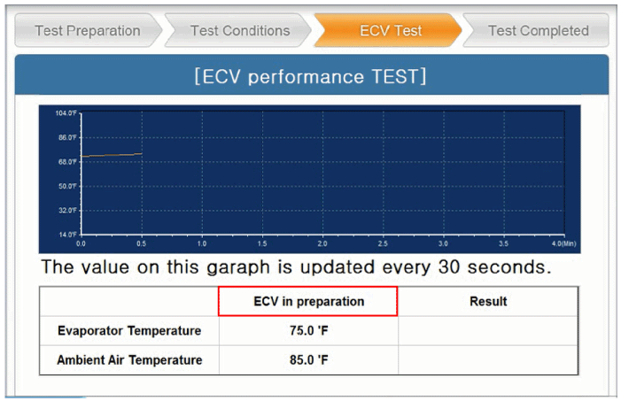
| 4. |
Start inspection
[ECV5]
[ECV6]
|

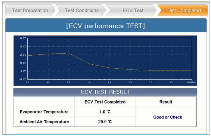
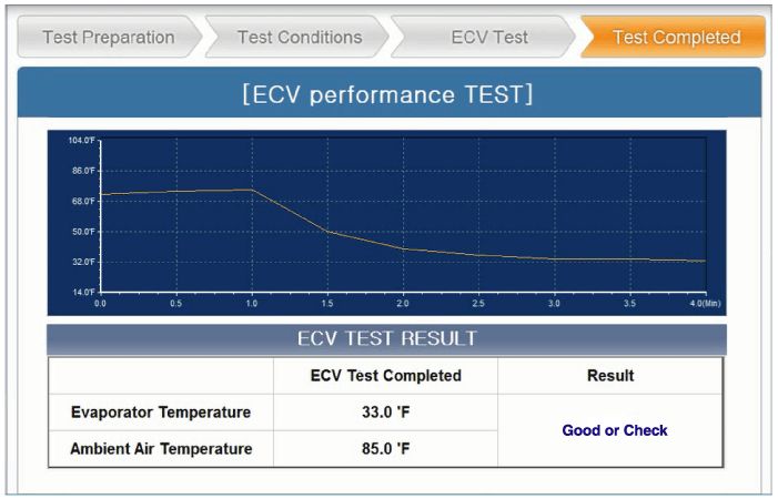
| 5. |
Check the result of inspection and click 'Check Detail' if
it's 'Check'. Follow the instruction and inspect ECV again from the
first step.
[ECV7]
[ECV8]
|
| Disassembly |
| 1. |
Disconnect the negative cable from the battery. |
| 2. |
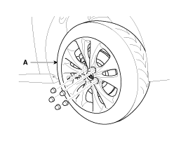
Remove the front right tire (A) from front hub.
|
| 3. |
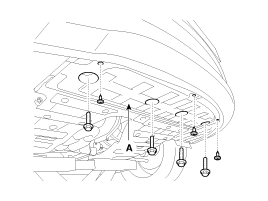
Remove the under cover (A).
|
| 4. |
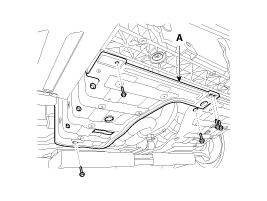
Remove the side cover (A).
|
| 5. |
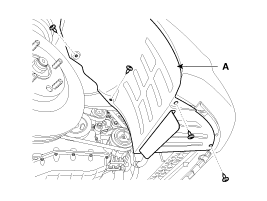
Remove the wheel house (A).
|
| 6. |
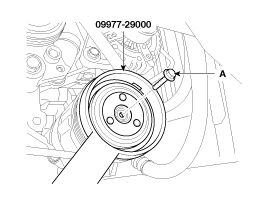
Remove the center bolt (A) while holding the disc & hub
assembly with a commercially available disc & hub assembly bolt
remover; Special tool number 09977-29000.
|
| 7. |
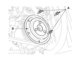
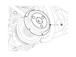
Loosen the disc & hub assembly mounting screws (A) and then remove the disc & hub assembly (B).
|
| 8. |
Remove the drive belt.
|
| 9. |
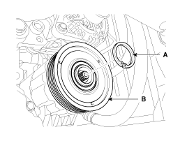
Remove retainer ring (A) with retainer ring pliers and then remove the pulley (B).
|

| 10. |
Reassemble the compressor clutch in the reverse order of disassembly, and note these items :
|
 Compressor Components and Components Location
Components
1. Screw2. Bolt3. Limiter Assembly4. Retainer Ring5. Pulley6. Connector Bracket7. Compressor Assembly
...
 Condenser Components and Components Location
Component Location
...
See also:
IMS (Integrated Memory System) module Repair procedures
Removal
1.
Remove the negative (-) battery terminal.
2.
Remove the driver seat in the car.
(Refer to Body - "Front Seat Assembly")
3.
Remove the IMS module (A) after loosening 3 screws in ...
TJ Joint Repair procedures
Replacement
•
Special grease must be applied to the driveshaft joint. Do not substitute with another type of grease.
•
The boot band should be replaced with a ne ...
Components and Components Location
Components
1. Gear knob & Gear boots2. Console upper tray complete3. Center facia side garnish [RH]4. Center facia side garnish [LH]5. Console extension cover [RH]6. Console extension cover [ ...
Categories
Hyundai Azera Manuals

© 2011-2026 Copyright www.hgmanual.com