 Hyundai Azera: Front Strut Assembly Repair procedures
Fifth generation HG (2011–2026) / Hyundai Azera 2011-2026 Service Manual / Suspension System / Front Suspension System / Front Strut Assembly Repair procedures
Hyundai Azera: Front Strut Assembly Repair procedures
Fifth generation HG (2011–2026) / Hyundai Azera 2011-2026 Service Manual / Suspension System / Front Suspension System / Front Strut Assembly Repair procedures
Fifth generation HG (2011–2026) / Hyundai Azera 2011-2026 Service Manual / Suspension System / Front Suspension System / Front Strut Assembly Repair procedures
| Replacement |
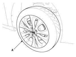
| 1. |
Remove the front wheel & tire (A).
|

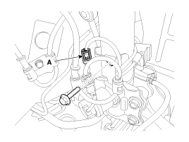
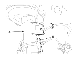
| 2. |
Remove the variable damper connector (A) & bracket (B).
|
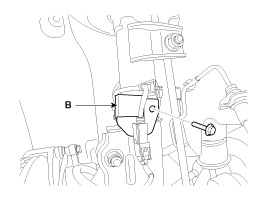
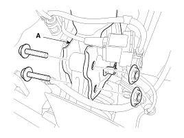
| 3. |
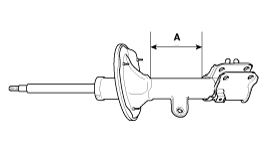
Remove the wheel speed sensor & bracket (A) from the front strut assembly by loosening bolts.
|
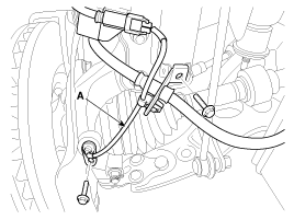
| 4. |
Disconnect the stabilizer link (B) with the front strut assembly (A) after loosening the nut.
|
| 5. |
Disconnect the front strut assembly (A) with the knuckle by loosening the bolt & nut.
|
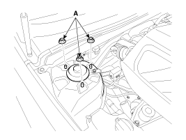
| 6. |
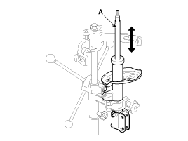
Loosen the strut upper locking nuts (A) and than remove the front strut assembly.
|
| 7. |
Installation is the reverse of removal. |
| Disassembly |
| 1. |
Under the condition of fixed strut (A) on the SST (09546-26000), remove the front strut self-locking nut (B).
|
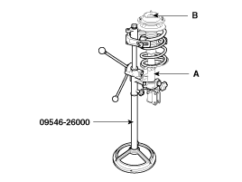
| 2. |
Remove the insulator, spring seat, coil spring and dust cover from the strut assembly |
| Inspection |
| 1. |
Check the strut bearing for wear and damage. |
| 2. |
Check the spring upper and lower seat for damage and deterioration. |
| 3. |
Compress and extend the piston rod (A) and check that there is no abnormal resistance or unusual sound during operation.
|
Disposal
| 1. |
Fully extend the piston rod. |
| 2. |
Drill a hole on the (A) section to remove gas form the cylinder.
|
 Front Strut Assembly Components and Components Location
Components
1. Dust cover2. Upper locking nut3. Self locking nut4. Space5. Insulator6. Spring upper seat7. Spring upper pad8. Strut dust cover & Bumper rubber9. Coil spring10. Spring lower pad ...
 Front Lower Arm Repair procedures
Replacement
1.
Remove the front wheel & tire (A).
Tightening torque:
88.3 ~ 107.9N.m (9.0 ~ 11.0kgf.m, 65.1 ~ 79.6lb-ft)
Be careful not to damage to the hub bolts ...
See also:
Speakers Repair procedures
Inspection
1.
Troubleshooting for Speaker
(1)
Basic inspection of speaker
Inspect the sound from speaker after verifying that the
speaker mounting screws are removed and the wiring connector ...
Glove Box Housing Components and Components Location
Component Location
1. Glove box housing
...
Using Bluetooth® Wireless Technology Audio Mode
Playing/Pausing Bluetooth® Wireless Technology Audio
Once a Bluetooth® Wireless Technology device is connected, the mode will automatically
start.
While playing, press the key to
pause and pr ...
Categories
Hyundai Azera Manuals

© 2011-2026 Copyright www.hgmanual.com