
 Hyundai Azera: Compass function
Fifth generation HG (2011–2026) / Hyundai Azera 2011-2026 Owners Manual / Features of your vehicle / Mirrors / Compass function
Hyundai Azera: Compass function
Fifth generation HG (2011–2026) / Hyundai Azera 2011-2026 Owners Manual / Features of your vehicle / Mirrors / Compass function
The Compass can be turned ON and OFF and will remember the last state when the ignition is cycled. To turn the display feature ON/OFF:
1. Press and release the button within 1 second to turn the display feature OFF.
2. Press and release the button again within 1 second to turn the display back ON.
Additional options can be set with press and hold sequences of the button and are detailed below.
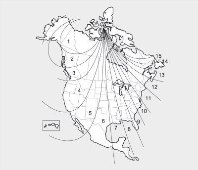
There is a difference between magnetic north and true north. The compass in the mirror can compensate for this difference when it knows the Magnetic Zone in which it is operating. This is set either by the dealer or by the user. The operating Zone Numbers for North America are shown in the figure on the following section.
To adjust the Zone setting:
1. Determine the desired Zone Number based upon your current location on the
Zone Map.
2. Press and hold the button for 6 seconds, the current Zone Number will appear
on the display.
3. Pressing and holding the button again will cause the numbers to increment (Note:
they will repeat …13, 14, 15, 1, 2, …). Releasing the button when the desired Zone
Number appears on the display will set the new Zone.
4. Within about 5 seconds the compass will start displaying a compass heading again.
There are some conditions that can cause changes to the vehicle magnets, such as installing a ski rack or a CB antenna. Body repair work on the vehicle can also cause changes to the vehicle's magnetic field. In these situations, the compass will need to be re-calibrated to quickly correct these changes. To re-calibrate the compass:
1. Press and hold the  button for
more than 9 seconds. When the compass memory is cleared a "C" will appear in the
display.
2. To calibrate the compass, drive the vehicle in 2 complete circles at less than
5 mph (8 km/h).
 Automatic-dimming function
Your mirror will automatically dim upon detecting glare from the vehicles traveling
behind you. The autodimming function can be controlled by the Dimming ON/OFF button:
1. Pressing and holding the b ...
 Integrated HomeLink® Wireless Control System
The HomeLink® Wireless Control System provides a convenient way to replace up
to three hand-held radiofrequency (RF) transmitters with a single built-in device.
This innovative feature will learn t ...
See also:
Radiator Repair procedures
Removal and Installation
1.
Remove the radiator upper hose and lower hose.
(Refer to Cooling System - "Radiator Hose")
2.
Remove the cooling fan assembly.
(Refer to Cooling System - "Cooli ...
CVVT (Continuously Variable Valve Timing) System Description and Operation
Description
Continuous Variable Valve Timing (CVVT) system advances or
retards the valve timing of the intake and exhaust valve in accordance
with the ECM control signal which is calculated by ...
Schematic Diagrams
Circuit Diagram (1)
Circuit Diagram (2)
Circuit Diagram (3)
SRSCM Connector terminal
Pin Function (Connector A)Pin Function (Connector B)1Ignition1Seat belt pretensioner [Driver] Hig ...
Categories
Hyundai Azera Manuals
