
 Hyundai Azera: Brake Pedal Repair procedures
Fifth generation HG (2011–2026) / Hyundai Azera 2011-2026 Service Manual / Brake System / Brake System / Brake Pedal Repair procedures
Hyundai Azera: Brake Pedal Repair procedures
Fifth generation HG (2011–2026) / Hyundai Azera 2011-2026 Service Manual / Brake System / Brake System / Brake Pedal Repair procedures
Fifth generation HG (2011–2026) / Hyundai Azera 2011-2026 Service Manual / Brake System / Brake System / Brake Pedal Repair procedures
| Removal |
| 1. |
Turn ignition switch OFF and disconnect the negative (-) battery cable. |
| 2. |
Remove the crash pad lower panel.
|
| 3. |
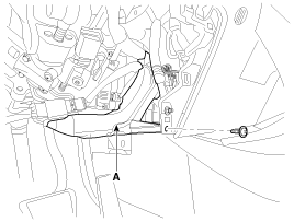
Remove the shower duct (A).
|
| 4. |
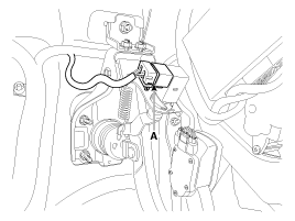
Disconnect the stop lamp switch connector (A).
|
| 5. |
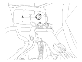
Remove the brake pedal member mounting nut (B).
|
| 6. |
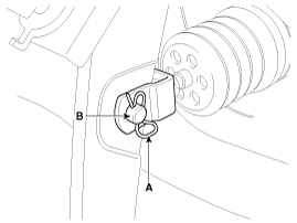
Remove the snap pin (A) and clevis pin (B).
|
| 7. |
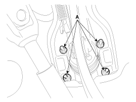
Remove the brake pedal member assembly mounting nuts (A) and then remove the brake pedal assembly.
|
| Inspection |
| 1. |
Check the bushing for wear. |
| 2. |
Check the brake pedal for bending or twisting. |
| 3. |
Check the brake pedal return spring for damage. |
| 4. |
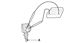
Check the stop lamp switch.
|
| Installation |
| 1. |
Pre-tighten the bracket fixing bolt (A) in dash panel.
|
| 2. |
Install the brake booster and brake pedal member fixing nuts (A) securely.
|
| 3. |
Tighten the bolt (A) securely in dash panel.
|
| 4. |
Install the snap pin (A) and clevis pin (B).
|

| 5. |
Install the stop lamp switch securely. |
| 6. |
Connect the stop lamp switch connector (A).
|
| 7. |
Adjust the brake pedal height and free play. |
| 8. |
Check the brake pedal operation after installing the brake pedal. |
| 9. |
Install the shower duct (A).
|
| 10. |
Install the crash pad lower panel. |
| 11. |
Reconnect the battery negative cable. |
| Adjustment |
| Stop lamp switch clearance adjustment |
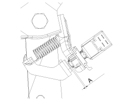
If the gap between stop lamp switch and bracket is not 1.0 ~ 2.0mm(0.04~ 0.08in), conform to below.
| 1. |
Disconnect the stop lamp switch connector (A).
|
| 2. |
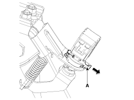
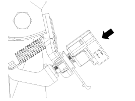
Pull the locking plate (A) as indicated by the arrow.
|
| 3. |
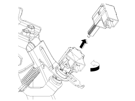
Turn stop lamp switch 45° counterclockwise and remove it.
|
| 4. |
Fix the brake pedal arm and insert fully the stop lamp switch as hiding contact part.
|
| 5. |
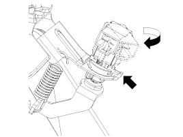
After inserting, turn the stop switch (A) 45° clockwise, and then assemble locking plate (B) by pushing.
|
| 6. |
Confirm the gap between stop lamp switch and bracket.
|
| 7. |
Connect the stop lamp switch connector.
|
 Brake Pedal Components and Components Location
Components
1. Cowl bracket2. Brake pedal member assembly3. Stop lamp switch4. Return spring5. Brake pedal stopper6. Clevis pin7. Snap pin8. Brake pedal
...
 Front Disc Brake Components and Components Location
Components
1. Guide rod bolt2. Bleed screw3. Caliper carrier4. Caliper body5. Inner pad shim6. Brake pad7. Pad retainer
...
See also:
Specifications
Specification
Smart Key Unit
ItemsSpecificationRated voltageDC 12VOperating voltageDC 9 ~ 16VOperating temperature-30°C ~ 80°C (-22°F ~ 176°F)LoadMax. 6mA
Smart Key FOB
ItemsSpecificationB ...
Front Seat Frame Assembly Repair procedures
Replacement
•
Use a plastic panel removal tool to remove interior trim pieces to protect from marring the surface.
•
Take care not to bend or scratch the trim and ...
Outside Rear View Mirror Components and Components Location
Component Location
1. Outside rear view mirror
...
Categories
Hyundai Azera Manuals

© 2011-2026 Copyright www.hgmanual.com