 Hyundai Azera: Front Disc Brake Repair procedures
Fifth generation HG (2011–2026) / Hyundai Azera 2011-2026 Service Manual / Brake System / Brake System / Front Disc Brake Repair procedures
Hyundai Azera: Front Disc Brake Repair procedures
Fifth generation HG (2011–2026) / Hyundai Azera 2011-2026 Service Manual / Brake System / Brake System / Front Disc Brake Repair procedures
Fifth generation HG (2011–2026) / Hyundai Azera 2011-2026 Service Manual / Brake System / Brake System / Front Disc Brake Repair procedures
| Removal |
| 1. |
Remove the front wheel & tire.
|
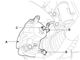
| 2. |
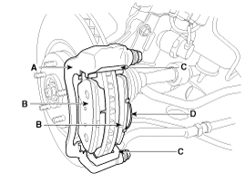
Loosen the hose eyebolt (C) and caliper mounting bolts (B), then remove the front caliper assembly (A).
|
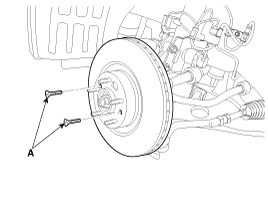
| 3. |
Remove the front brake disc by loosening the screws (A).
|
| Replacement |
Front brake pads
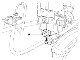
| 1. |
Remove the brake hose mounting bracket bolt (A).
|
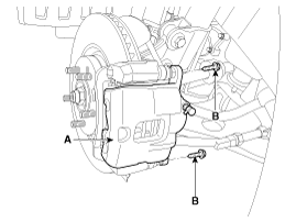
| 2. |
Loosen the guide rod bolt (B) and then remove caliper body (A).
|
| 3. |
Replace pad shim (D), pad retainers (C) and brake pads (B) in the caliper carrier (A).
|
| Inspection |
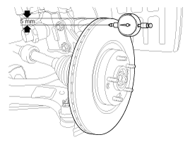
Front brake disc thickness check
| 1. |
Check the brake pads for wear and fade. |
| 2. |
Check the brake disc for damage and cracks. |
| 3. |
Remove all rust and contamination from the surface, and
measure the disc thickness at 8 points, at least, of same distance (5mm)
from the brake disc outer circle.
|
| 4. |
If wear exceeds the limit, replace the discs and pad assembly left and right of the vehicle. |
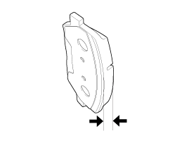
Front Brake Pad Check
| 1. |
Check the pad wear. Measure the pad thickness and replace it, if it is less than the specified value.
|
| 2. |
Check that grease is applied, to sliding contact points and the pad and backing metal for damage.
|
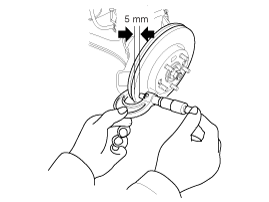
Front brake disc runout check
| 1. |
Place a dial gauge about 5mm (0.2 in.) from the outer circumference of the brake disc, and measure the runout of the disc.
|
| 2. |
If the runout of the brake disc exceeds the limit specification, replace the disc, and then measure the runout again. |
| 3. |
If the runout does not exceed the limit specification,
install the brake disc after turning it 180° and then check the runout
of the brake disc again. |
| 4. |
If the runout cannot be corrected by changing the position of the brake disc, replace the brake disc. |
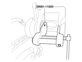
| Installation |
| 1. |
Installation is the reverse of removal. |
| 2. |
Use a SST (09581-11000) when installing the brake caliper assembly.
|
| 3. |
After installation, bleed the brake system.
(Refer to Brake system bleeding) |
 Front Disc Brake Components and Components Location
Components
1. Guide rod bolt2. Bleed screw3. Caliper carrier4. Caliper body5. Inner pad shim6. Brake pad7. Pad retainer
...
 Rear Disc Brake Components and Components Location
Components
1. Guide rod bolt2. Bleed screw3. Caliper carrier4. Caliper body5. Inner pad shim6. Brake pad7. Pad retainer
...
See also:
Intake Air Temperature Sensor (IATS) Specifications
Specification
TemperatureResistance (k?)°C°F-40-4040.93 ~ 48.35-20-413.89 ~ 16.030325.38 ~ 6.0910503.48 ~ 3.9020682.31 ~ 2.57401041.08 ~ 1.21601400.54 ~ 0.66801760.29 ~ 0.34
...
Automatic Transaxle Repair procedures
Removal
1.
Engine cover.
(Refer to Engine Mechanical System - "Engine cover")
2.
Air cleaner assembly and air duct.
(Refer to Engine Mechanical System - "Air cleaner")
3.
Battery and ba ...
Maintenance service
You should exercise the utmost care to prevent damage to your vehicle and injury
to yourself whenever performing any maintenance or inspection procedures.
Should you have any doubts concerning the i ...
Categories
Hyundai Azera Manuals

© 2011-2026 Copyright www.hgmanual.com