
 Hyundai Azera: Photo Sensor Repair procedures
Fifth generation HG (2011–2026) / Hyundai Azera 2011-2026 Service Manual / Heating,Ventilation, Air Conditioning / Air Conditioning System / Photo Sensor Repair procedures
Hyundai Azera: Photo Sensor Repair procedures
Fifth generation HG (2011–2026) / Hyundai Azera 2011-2026 Service Manual / Heating,Ventilation, Air Conditioning / Air Conditioning System / Photo Sensor Repair procedures
Fifth generation HG (2011–2026) / Hyundai Azera 2011-2026 Service Manual / Heating,Ventilation, Air Conditioning / Air Conditioning System / Photo Sensor Repair procedures
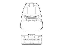
| Inspection |
| 1. |
Ignition "ON" |
| 2. |
Using the scan tool. |
| 3. |
Emit intensive light toward photo sensor using a lamp, and check the output voltage change. |
| 4. |
The voltage will rise with higher intensive light and reduce with lower intensive light.
|
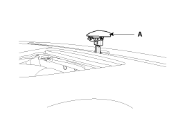
| Replacement |
| 1. |
Disconnect the negative (-) battery terminal. |
| 2. |
With the (-) driver, remove the photo sensor (A) from the center of defrost nozzle.
|
| 3. |
Install in the reverse order of removal. |
 Photo Sensor Description and Operation
Description
1.
The photo sensor is located at the center of defrost nozzle.
2.
The photo sensor contains a photovoltaic (sensitive to
sunlight) diode. The solar radiation received by its lig ...
 Ambient Sensor Description and Operation
Description
1.
The ambient temperature sensor is located at the front of the
condenser and detects ambient air temperature. It is a negative type
thermistor resistance will increase with lower ...
See also:
SRS Control Module (SRSCM) Repair procedures
Removal
1.
Remove the ignition key from the vehicle.
2.
Disconnect the battery negative cable and wait for at least three minutes before beginning work.
3.
Remove the floor console.
(Ref ...
Basic Mode Screen
(1) Mode Displays currently operating mode.
(2) Operation State From Repeat / Shuffle / Scan, displays the currently operating
function.
(3) Track Info Displays information about the cu ...
Front Oil Seal Components and Components Location
Components
1. Front oil seal
...
Categories
Hyundai Azera Manuals

© 2011-2026 Copyright www.hgmanual.com