 Hyundai Azera: Schematic Diagrams
Fifth generation HG (2011–2026) / Hyundai Azera 2011-2026 Service Manual / Body Electrical System / IMS (Integrated Memory) / Schematic Diagrams
Hyundai Azera: Schematic Diagrams
Fifth generation HG (2011–2026) / Hyundai Azera 2011-2026 Service Manual / Body Electrical System / IMS (Integrated Memory) / Schematic Diagrams
Fifth generation HG (2011–2026) / Hyundai Azera 2011-2026 Service Manual / Body Electrical System / IMS (Integrated Memory) / Schematic Diagrams
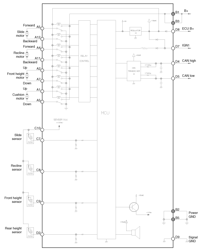
| Circuit Diagram |
| Input/Output Specification |
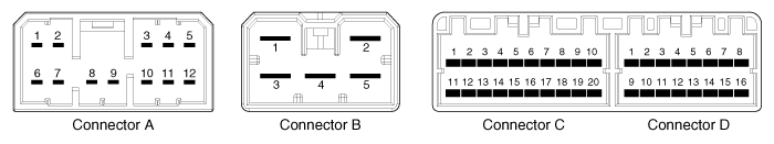
| Connector Pin Lay Out |
IMS input/output pin information
| No | Signal Name | I/O | Contents | Remark |
| A1 | Cushion motor FR | O | Cushion motor FR output | |
| A2 | FR height motor up | O | FR height motor up output | |
| A3 | RR height motor up | O | RR height motor up output | |
| A4 | Recline motor FR | O | Recline motor FR output | |
| A5 | Slide motor FR | O | Slide motor FR output | |
| A6 | Cushion motor RR | O | Cushion motor RR output | |
| A7 | FR height motor down | O | FR height motor down output | |
| A8 | - | - | - | |
| A9 | - | - | - | |
| A10 | RR height motor down | O | RR height motor down output | |
| A11 | Recline motor RR | O | Recline motor RR output | |
| A12 | Slide motor RR | O | Slide motor RR output | |
| B1 | GND(Power) | I | Power B+ for operating motor | |
| B2 | GND (Power) | I | Power GND for operating motor | |
| B3 | B+(Power) | I | Power B+ for operating motor | |
| B4 | - | - | - | |
| B5 | GND (Power) | I | Power GND for operating motor | |
| C1 | - | - | - | |
| C2 | - | - | - | |
| C3 | Slide FR manual switch | I | Slide FR manual switch input | On : GND |
| C4 | Recline FR manual switch | I | Recline FR manual switch input | On : GND |
| C5 | FR height up manual switch | I | FR height up manual switch input | On : GND |
| C6 | RR height up manual switch | I | RR height up manual switch input | On : GND |
| C7 | Slide motor sensor | I | Slide motor sensor input | Pulse signal |
| C8 | Recline motor sensor | I | Recline motor sensor input | Pulse signal |
| C9 | FR height motor sensor | I | FR height motor sensor input | Pulse signal |
| C10 | Sensor Vcc(Seat) | O | VCC for operating sensor | 5V |
| C11 | - | - | - | |
| C12 | - | - | - | |
| C13 | - | - | - | |
| C14 | - | - | - | |
| C15 | - | - | - | |
| C16 | - | - | - | |
| C17 | - | - | - | |
| C18 | - | - | - | |
| C19 | - | - | - | |
| C20 | - | - | - | |
| D1 | - | - | - | |
| D2 | RR height up sensor | I | RR height up motor sensor | Pulse signal |
| D3 | - | - | - | |
| D4 | CAN high | I/O | CAN | |
| D5 | CAN low | I/O | CAN | |
| D6 | - | - | - | |
| D7 | IGN1 | I | IGN1 input | BAT |
| D8 | B+(ECU) | I | ECU power input | BAT |
| D9 | GND(ECU) | I | ECU GND | |
| D10 | - | - | - | |
| D11 | - | - | - | |
| D12 | - | - | - | |
| D13 | - | - | - | |
| D14 | - | - | - | |
| D15 | - | - | - | |
| D16 | - | - | - |
| Communication System |
 Components and Components Location
Component Location
1. Seat Memory Unit (IMS)2. IMS control switch3. IMS driver power seat control
...
 Description and Operation
Description
system outline
An optimal seat position set by a driver can be memorized in
Power seat unit by IMS SW, which enables restoration of seat position
set by the driver despite
Playi ...
See also:
Specifications
Specifications
Fuel Delivery System
ItemsSpecificationFuel TankCapacity70 lit. (18.5 U.S.gal., 74.0 U.S.qt., 61.6 Imp.qt.)Fuel FilterTypePaper typeFuel PressureLow Pressure Fuel Line480 ~ 520 ...
Center Muffler Repair procedures
Removal and Installation
1.
Disconnect the battery negative terminal.
(Refer to Engine Electrical System - "Battery")
2.
Remove the catalytic converter & center muffler assembly (A).
...
Drive Plate Repair procedures
Removal and Installation
1.
Remove the automatic transaxle.
(Refer to Automatic Transaxle System - "Automatic Transaxle")
2.
Remove the adapter plate (B) and the drive plate (A).
Tighteni ...
Categories
Hyundai Azera Manuals

© 2011-2026 Copyright www.hgmanual.com