 Hyundai Azera: Schematic Diagrams
| Schematic Diagram |
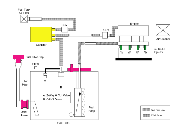
Canister
Canister is filled with charcoal and absorbs evaporated vapor
in fuel tank. The gathered fuel vapor in canister is drawn into the
intake manifold by the ECM/PCM when appropriate conditions are set.
Purge Control Solenoid Valve (PCSV)
Purge Control Solenoid Valve (PCSV) is installed in the
passage connecting canister and intake manifold. It is a duty type
solenoid valve and is operated by ECM/PCM signal.
To draw the absorbed vapor into the intake manifold, the ECM/PCM will open the PCSV, otherwise the passage remains closed.
Fuel Filler Cap
A ratchet tightening device on the threaded fuel filler cap
reduces the chances of incorrect installation, seals the fuel filler.
After the gasket on the fuel filler cap and the fill neck flange make
contact, the ratchet produces a loud clicking noise indicating the seal
has been set.
Fuel Tank Pressure Sensor (FTPS)
The Fuel Tank Pressure Sensor (FTPS) is an integral part of
the monitoring system. The FTPS checks Purge Control Solenoid Valve
(PCSV) operation and leaks in the Evaporative Emission Control System by
monitoring pressure and vacuum level in the fuel tank during PCSV
operating cycles.
Canister Close Valve (CCV)
The Canister Close Valve (CCV) is located between the
canister and the fuel tank air filter. It closes off the air inlet to
the canister for the Evaporative Emissions System and also prevents fuel
vapors from escaping from the Canister when the vehicle is not
operating.
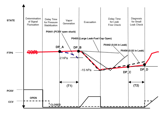
Evaporative System Monitoring
Evaporative Emission Control Monitoring System consists of
fuel vapor generation, evacuation, and leakage check step. At first, the
OBD-II system checks if vapor generation due to fuel temperature is
small enough to start monitoring. Then it evacuates the evaporative
system by means of PCSV with ramp in order to maintain a certain vacuum
level. The final step is to check if there is vacuum loss by any leakage
of the system.
Vapor Generation Checking
During stabilization period, the PCSV and the CCV are closed.
The system pressure is measured as starting pressure (DP_A). After a
certain defined period (T1), the system pressure (DP_B) is measured
again and the difference from the starting pressure is calculated. If
this difference (DP_B - DP_A) is bigger than a threshold, there should
be excessive vapor and the monitor is aborted for next checking. On the
contrary, if the difference is lower than another negative threshold,
PCSV is regarded as malfunction such as clogged at open position.
Evacuation
PCSV is opened with a certain ramp for the pressure to reach
down to a certain level. If pressure can’t be lowered below a
threshold, the system is regarded as fuel cap-opened or having a large
leakage.
Leaking Checking
PCSV is closed and the system waits for a period to get
stabilized pressure. During checking period (T2), the system measures
the beginning and the end of the system pressure (DP_C, DP_D). The
diagnosis value is the pressure difference corrected by natural vapor
generation (DP_B - DP_A) rate from the vapor generation checking step.
Components Location
| 1. Purge Control Solenoid Valve (PCSV) 2. Vapor line 3. ORVR valve 4. Fuel tank air filter | 5. Canister Close Valve (CCV) 6. Canister 7. Fuel Tank Pressure Sensor (FTPS) |
Evaporative System Monitoring
Evaporative And ORVR Emission Control System
This system consists of below items;
| - |
Fill vent valve |
| - |
Fuel shut-off valve |
| - |
Fuel cut valve (for roll over) |
| - |
Two way valve (pressure/vacuum relief) |
| - |
Fuel liquid/vapor separator which is installed beside the filler pipe |
| - |
Charcoal canister which is mounted under the rear floor LH side member and protector |
| - |
Tubes and miscellaneous connections |
While refueling, ambient air is drawn into the filler pipe so
as not to emit fuel vapors in the air. The fuel vapor in the tank is
then forced to flow into the canister via the fill vent valve. The fuel
liquid/vapor separator isolates liquid fuel and passes the pure vapor to
the charcoal canister.
While the engine is operating, the trapped vapor in the
canister is drawn into the intake manifold and then into the engine
combustion chamber. According to this purge process, the charcoal
canister is purged and recovers its absorbing capability.
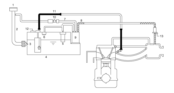
| 1. Fuel Filler Cap 2. Fuel Filler Pipe 3. Fuel Shut-OFF Valve 4. Fuel Tank 5. ORVR Valve 6. 2-Way & Cut Valve 7. Evaporative Hose | 8. Evaporative Hose 9. Canister 10. Canister Close Valve (CCV) 11. Fuel Feed Line 12. Fuel Tank Pressure Sensor (FTPS) 13. Purge Control Solenoid Valve (PCSV) |
 Description and Operation
Description
Evaporative Emission Control System prevents fuel vapor
stored in fuel tank from vaporizing into the atmosphere. When the fuel
evaporates in the fuel tank, the vapor passes through ...
 Canister Repair procedures
Removal
1.
Turn the ignition switch OFF and disconnect the negative (-) battery cable.
2.
Disconnect the ventilation hose (A) from the fuel tank air filter.
3.
Disconnect the vapor tube q ...
See also:
Special Service Tools
Special Service Tools
Tool(Number and Name)IllustrationUse09581-11000Piston expanderSpreading the front disc brake piston.
...
Passenger Airbag (PAB) Module Components and Components Location
Components
...
Description and Operation
Description
Evaporative Emission Control System prevents fuel vapor
stored in fuel tank from vaporizing into the atmosphere. When the fuel
evaporates in the fuel tank, the vapor passes through ...
Categories
Hyundai Azera Manuals

© 2011-2025 Copyright www.hgmanual.com