
 Hyundai Azera: Steering Column and Shaft Repair procedures
Fifth generation HG (2011–2026) / Hyundai Azera 2011-2026 Service Manual / Steering System / Electric Power Steering / Steering Column and Shaft Repair procedures
Hyundai Azera: Steering Column and Shaft Repair procedures
Fifth generation HG (2011–2026) / Hyundai Azera 2011-2026 Service Manual / Steering System / Electric Power Steering / Steering Column and Shaft Repair procedures
Fifth generation HG (2011–2026) / Hyundai Azera 2011-2026 Service Manual / Steering System / Electric Power Steering / Steering Column and Shaft Repair procedures
| Replacement |
| 1. |
Disconnect the battery negative cable from the battery and then wait for at least 30 seconds. |
| 2. |
Turn the steering wheel so that the front wheels can face straight ahead. |
| 3. |
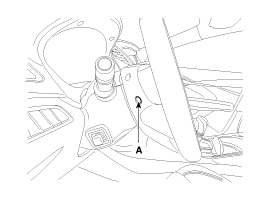
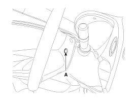
Push the pin (A) and then disconnect the airbag module from the steering wheel.
|
| 4. |
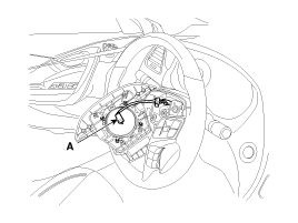
Disconnect the airbag module connector (A) & horn connector (B) and then remove the airbag module from the steering wheel.
|
| 5. |
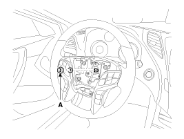
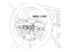
Disconnect the lock nut (A) & connector (B) and then remove the steering wheel by using special service tools. (09561-11001)
|

| 6. |
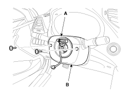
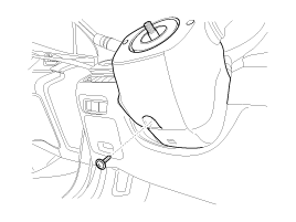
Loosen the screw and then remove the steering column upper (A) and lower shroud (B).
|
| 7. |
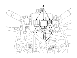
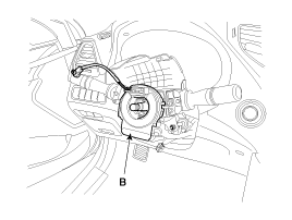
Disconnect the connector (A) and then remove the clock spring (B).
|
| 8. |
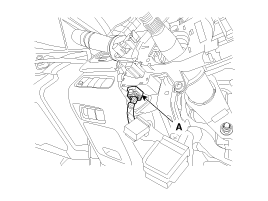
Disconnect the connector (A).
|
| 9. |
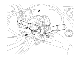
Loosen the screw and then remove the multifunction switches (A).
|
| 10. |
Remove the crash pad side cover, Fuse box cover and lower crash pad.
|
| 11. |
Loosen the screw and then remove the shower tilt (A).
|
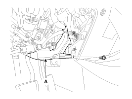
| 12. |
Loosen the bolt (A) and then disconnect the universal joint assembly from the pinion of th
|
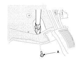
| 13. |
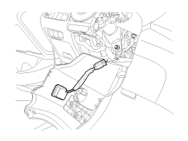
Disconnect all connectors connected the steering column & EPS unit assembly. |
| 14. |
Remove the steering column & EPS unit assembly by loosening the mounting bolt (A) and nuts (B).
|
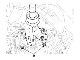
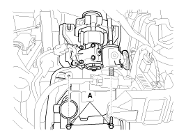
| 15. |
Installation is the reverse of the removal. |
| 16. |
Conduct the "ASP Calibration" and "EPS Type Recognition" by GDS.
(Refer to Electric Power Steering - "ASP calibration or EPS type recognition") |
| 17. |
Conduct the "MDPS TEST (Motor Driven Power Steering)" by GDS.
(Refer to Electric Power Steering - "MDPS Performance Inspection") |
| Universal joint assembly |
| 1. |
Loosen the bolt (A) and then disconnect the universal joint assembly from the steering column assembly.
|
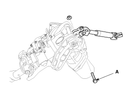
| 2. |
Reassembly is the reverse of the disassembly.
|
| Inspection |
| 1. |
Check the steering column for damage and deformation. |
| 2. |
Check the steering column for damage and deformation. |
| 3. |
Check the join bearing for damage and wear. |
| 4. |
Check the tilt bracket for damage and cracks. |
| 5. |
Check the key lock assembly for proper operation and replace it if necessary. |
 Repair procedures
General Inspection
After or before servicing the EPS system, perform the
troubleshooting and test procedure as follows. Compare the system
condition with normal condition in the table below and ...
 Steering Gear box Components and Components Location
Components
1. Tie-rod end2. Lock nut3. Bellows clip4. Bellows5. Tie rod6. Rack bar7. Dust packing8. Dust cap9. Oil seal10. Pinion plug11. Pinion assembly12. Yoke plug13. Yoke spring14. Support yo ...
See also:
Trunk Trim Repair procedures
Replacement
•
Use a plastic panel removal tool to remove interior trim pieces to protect from marring the surface.
•
Take care not to bend or scratch the trim and ...
Heater & A/C Control Unit(Full Automatic) Repair procedures
Inspection
Self diagnosis
1.
Self-diagnosis process
2.
How to read self-diagnostic code.
After the display panel flickers three times every 0.5
second, the corresponding fault code flicker ...
IMS (Integrated Memory System) module Repair procedures
Removal
1.
Remove the negative (-) battery terminal.
2.
Remove the driver seat in the car.
(Refer to Body - "Front Seat Assembly")
3.
Remove the IMS module (A) after loosening 3 screws in ...
Categories
Hyundai Azera Manuals

© 2011-2026 Copyright www.hgmanual.com