
 Hyundai Azera: Description and Operation
Fifth generation HG (2011–2026) / Hyundai Azera 2011-2026 Service Manual / Body Electrical System / Multifunction switch / Description and Operation
Hyundai Azera: Description and Operation
Fifth generation HG (2011–2026) / Hyundai Azera 2011-2026 Service Manual / Body Electrical System / Multifunction switch / Description and Operation
Fifth generation HG (2011–2026) / Hyundai Azera 2011-2026 Service Manual / Body Electrical System / Multifunction switch / Description and Operation
| Description |
| Communication network diagram |
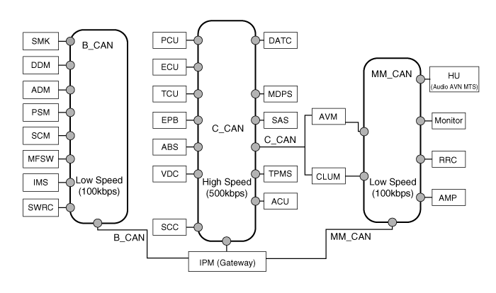
| Abbreviation | Explanation |
| C_CAN | Chassis Controller Area Network |
| B_CAN | Body Controller Area Network |
| MM_CAN | Multi media Controller Area Network |
| SMK | Smart Key ECU |
| DDM | Driver Door Module |
| ADM | Assist Door Module |
| PSM | Power Seat Module |
| SCM | Steering Column Module |
| IMS | Integrated Memory System |
| MFSW | Multi-Function Switch |
| SWRC | Steering Wheel Remote Controller |
| PCU | Power-train Control Unit |
| ECU | Engine Control Unit |
| TCU | Transmission Control Unit |
| EPB | Electronic Parking Brake |
| ABS | Anti-lock Brake System |
| VDC | Vechile Stability Control |
| SCC | Smart Cruise Control |
| DATC | Dual Automatic Temp Control |
| MDPS | Motor Driven Power Steering |
| SAS | Steering Angle Sensor |
| TPMS | Tire Pressure Monitoring System |
| ACU | Airbag Control Unit |
| AVM | Around View Monitor |
| CLUM | Cluster Module |
| HU | Head Unit |
| RRC | Rear Remote Control |
| IPM | Intelligent itegrated Platform Module |
 Components and Components Location
Component (1)
1. Steering column2. Lighting switch3. Wiper switch4. Screw5. Clock spring
Component (2)
...
 Repair procedures
Inspection (With GDS)
1.
Check BCM input/output specification of multifunction switch
using the GDS. If the specification is abnormal, replace the lamp or
wiper switch.
2.
If diagnosis is ...
See also:
Knock Sensor (KS) Schematic Diagrams
Circuit Diagram
...
Evaporator Temperature Sensor Repair procedures
Inspection
1.
Ignition "OFF".
2.
Disconnect evaporator temperature sensor.
3.
Using the multi-tester, Measure resistance between terminal "1" and "2" of evaporator temperature sensor.
Spe ...
How vehicle audio works
AM and FM radio signals are broadcast from transmitter towers located around
your city. They are intercepted by the radio antenna on your vehicle. This signal
is then processed by the radio and se ...
Categories
Hyundai Azera Manuals

© 2011-2026 Copyright www.hgmanual.com