 Hyundai Azera: Passive Occupant Detection System (PODS-F) Repair procedures
Fifth generation HG (2011–2026) / Hyundai Azera 2011-2026 Service Manual / Restraint / SRSCM / Passive Occupant Detection System (PODS-F) Repair procedures
Hyundai Azera: Passive Occupant Detection System (PODS-F) Repair procedures
Fifth generation HG (2011–2026) / Hyundai Azera 2011-2026 Service Manual / Restraint / SRSCM / Passive Occupant Detection System (PODS-F) Repair procedures
Fifth generation HG (2011–2026) / Hyundai Azera 2011-2026 Service Manual / Restraint / SRSCM / Passive Occupant Detection System (PODS-F) Repair procedures
| Removal |
PODS-F ECU
| 1. |
Disconnect the battery negative cable, and wait for at least three minutes before beginning work. |
| 2. |
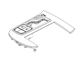
Remove the front passenger seat assembly.
|
| 3. |
Disconnect the PODS-F ECU connector. |
| 4. |
Remove the PODS-F ECU.
|
PODS-F Mat
| 1. |
Disconnect the battery negative cable, and wait for at least three minutes before beginning work. |
| 2. |
Remove the front passenger seat assembly.
|
| 3. |
Disconnect the PODS-F ECU connector. |
| 4. |
Remove the front seat cushion assembly.
|
| Installation |
PODS-F ECU
| 1. |
Install the PODS-F ECU on the Front seat track assembly. |
| 2. |
Connect the PODS-F ECU connector. |
| 3. |
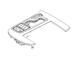
Install the front passenger seat assembly.
|
| 4. |
Reconnect the battery negative cable. |
| 5. |
After installing the PODS-F, confirm proper system operation :
|

PODS-F Mat
| 1. |
Install the PODS-F Mat equipped seat cushion assembly on the front seat assembly.
|
| 2. |
Connect the PODS-F mat connector. |
| 3. |
Install the front passenger seat assembly.
|
| 4. |
Reconnect the battery negative cable. |
| 5. |
After installing the PODS-F, confirm proper system operation :
|
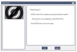
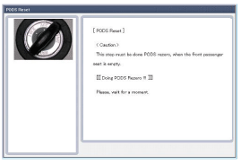
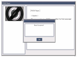
| PODS-F Zeroing procedure |
You should perform PODS-F reset procedure after service or
replacement about all part of the passenger seat. (Not included full
seat assembly)
| 1. |
Ignition “OFF”, connect GDS. |
| 2. |
Ignition “ON” & Engine “OFF”, select Airbag system and “PODS-F Reset” mode.
|
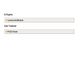
| 3. |
The GDS will show the two PODS-F Zeroing function steps.
|

| 4. |
Select product configuration.
|
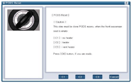
| 5. |
The PODS-F initialization procedure will be performed.
|

 Schematic Diagrams
Circuit Diagram (1)
Circuit Diagram (2)
Circuit Diagram (3)
SRSCM Connector terminal
Pin Function (Connector A)Pin Function (Connector B)1Ignition1Seat belt pretensioner [Driver] Hig ...
See also:
Vanity mirror lamp
Opening the lid of the vanity mirror will automatically turn on the mirror light.
CAUTION
To prevent unnecessary charging system drain, close the vanity mirror cover
after using the mirror. ...
Features of your vehicle
Satellite radio reception
You may experience difficulties in receiving XM™ satellite radio signals in the
following situations.
If you are driving in a tunnel or a covered parking area.
If ...
Vapor hose and fuel filler cap
The vapor hose and fuel filler cap should be inspected at those intervals specified
in the maintenance schedule. Make sure that a new vapor hose or fuel filler cap
is correctly replaced. ...
Categories
Hyundai Azera Manuals

� 2011-2026 Copyright www.hgmanual.com