 Hyundai Azera: Oil Pressure Switch Repair procedures
Fifth generation HG (2011–2026) / Hyundai Azera 2011-2026 Service Manual / Engine Mechanical System / Lubrication System / Oil Pressure Switch Repair procedures
Hyundai Azera: Oil Pressure Switch Repair procedures
Fifth generation HG (2011–2026) / Hyundai Azera 2011-2026 Service Manual / Engine Mechanical System / Lubrication System / Oil Pressure Switch Repair procedures
Fifth generation HG (2011–2026) / Hyundai Azera 2011-2026 Service Manual / Engine Mechanical System / Lubrication System / Oil Pressure Switch Repair procedures
| Removal and Installation |
| 1. |
Remove the water pipe.
(Refer to Cooling System - "Water Pipe") |
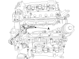
| 2. |
Remove the oil pressure switch (A).
|

| 3. |
Installation is in the reverse order of removal. |
| Inspection |
| 1. |
Check the continuity between the terminal and the body with an ohmmeter.
If there is no continuity, replace the oil pressure switch.
|
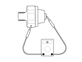
| 2. |
Check the continuity between the terminal and the body when
the fine wire is pushed. If there is continuity even when the fine wire
is pushed, replace the switch.
|
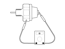
| 3. |
If there is no continuity when a 50 kpa (7psi) is applied
through the oil hole the switch is operaing properly. Check for air
leakage. If air leaks, the diaphragm is broken. Replace it. |
 Oil Pressure Switch Components and Components Location
Components
1. Oil cover2. Oil cover gasket3. Oil pressure switch
...
 Oil Level Gauge & Pipe Components and Components Location
Components
1. Oil level gauge2. Oil level gauge pipe3. O-ring
...
See also:
Integrated HomeLink® Wireless Control System
The HomeLink® Wireless Control System provides a convenient way to replace up
to three hand-held radiofrequency (RF) transmitters with a single built-in device.
This innovative feature will learn t ...
CVVT Oil Control Valve (OCV) Schematic Diagrams
Circuit Diagram
...
Radiator Components and Components Location
Components
1. Radiator2. Radiator mounting bracket3. Radiator cap4. Drain plug5. Mounting insulator
...
Categories
Hyundai Azera Manuals

© 2011-2026 Copyright www.hgmanual.com