
 Hyundai Azera: Power Window Switch Repair procedures
Fifth generation HG (2011–2026) / Hyundai Azera 2011-2026 Service Manual / Body Electrical System / Power Windows / Power Window Switch Repair procedures
Hyundai Azera: Power Window Switch Repair procedures
Fifth generation HG (2011–2026) / Hyundai Azera 2011-2026 Service Manual / Body Electrical System / Power Windows / Power Window Switch Repair procedures
Fifth generation HG (2011–2026) / Hyundai Azera 2011-2026 Service Manual / Body Electrical System / Power Windows / Power Window Switch Repair procedures
| Inspection |
Driver Power Window Switch
| 1. |
When checking the driver power window switch, select a vehicle type and "IPM" menu. |
| 2. |
Select "DDM (Driver Door Module)". |
| 3. |
Select option "Input/Output monitoring".
|
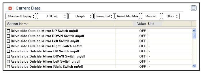
| 4. |
To check the input value of power window switch in force mode, select option "ACTUATION TEST".
|
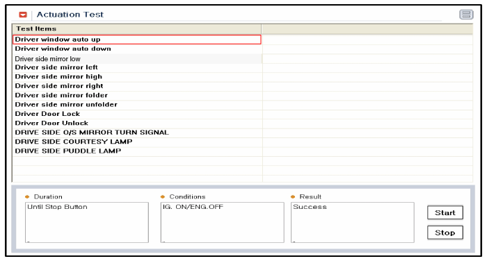
Assist Power Window Switch
| 1. |
When checking the assist power window switch, select a vehicle type and "IPM" menu. |
| 2. |
Select "ADM (Assist Door Module)". |
| 3. |
Select option "Input/Output monitoring".
|
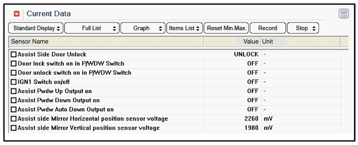
| 4. |
To check the input value of power window switch in force mode, select option "ACTUATION TEST".
|
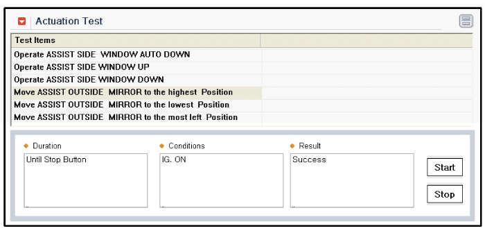
| Removal |
| Driver Power Window Switch |
| 1. |
Disconnect the negative(-) battery terminal. |
| 2. |
Remove the front door trim panel.
|
| 3. |
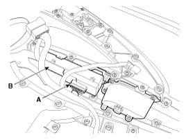
Disconnect the power window switch module connector (A) from the wiring harness.
|
| 4. |
Remove the power window switch module (B) from the door trim after loosening the mounting screws.
|

| Passenger Power Window Switch |
| 1. |
Disconnect the negative (-) battery terminal. |
| 2. |
Remove the front door trim panel.
|
| 3. |
Disconnect the connector from the power window switch module. |
| 4. |
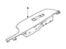
Remove the power window switch module (A) from the door trim after loosening the mounting screws.
|
| 5. |
Remove the power window switch after loosening screws. |
| Rear Power Window Switch |
| 1. |
Disconnect the negative (-) battery terminal. |
| 2. |
Remove the rear door trim panel.
|
| 3. |
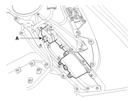
Disconnect the connector (A) from the power window switch module. |
| 4. |
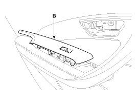
Remove the power window switch module (B) from the door trim after loosening the mounting screws.
|
| 5. |
Remove the power window switch (A) after loosening the fixing clip.
|
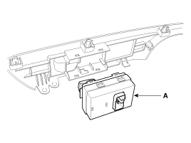
| Installation |
| 1. |
Install the power window switch module. |
| 2. |
Install the door trim panel after reconnecting the relevant connectors
|
 Power Window Switch Schematic Diagrams
Circuit Diagram
Driver Power Window Switch (1)
Driver Power Window Switch (2)
Passenger Power Window Swich
Rear Power Window Swich
...

See also:
Front Door Trim Components and Components Location
Component Location
1. Front door trim
...
Injector Drive Box (IDB) Repair procedures
Removal
1.
Turn the ignition switch off and disconnect the battery negative (-) cable.
2.
Disconnect the injector drive box (IDB) connector (A).
3.
Remove the air cleaner assembly.
(Refer ...
Hill-start assist control (HAC)
The main intent is to prevent the vehicle from rolling backwards while driving
uphill on an inclined surface. HAC holds the braking pressure built up by the driver
when the vehicle is stopped for 2 ...
Categories
Hyundai Azera Manuals

© 2011-2026 Copyright www.hgmanual.com