
 Hyundai Azera: General Information
Fifth generation HG (2011–2026) / Hyundai Azera 2011-2026 Service Manual / General Information / General Tightening Torque Table / General Information
Fifth generation HG (2011–2026) / Hyundai Azera 2011-2026 Service Manual / General Information / General Tightening Torque Table / General Information
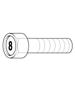
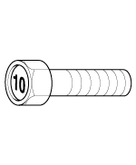
| Tightening Torque Table Of Standard Parts |
| BOLT (Nominal diameter) | NUT (Nominal diameter) | ||
|
|
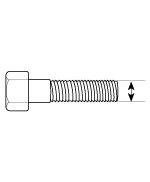
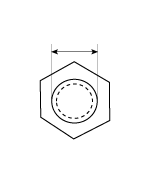
| BOLT/NUT Thin screw | Torque Nm (kg.m, Ib-ft) | |||
Nominal diameter. (mm) | Pitch [mm (in.) ] | 4T | 8T | 10T |
|
|
|
| |
| M5 | 0.8 (0.031) | 2.0 ~ 3.0 (0.2 ~ 0.3, 1.4 ~ 2.2) | 4.9 ~ 6.9 (0.5 ~ 0.7, 3.6 ~ 5.1) | 7.8 ~ 10.8 (0.8 ~ 1.1, 5.8 ~ 8.0) |
| M6 | 1 (0.039) | 2.9 ~ 4.9 (0.3 ~ 0.5, 2.2 ~ 3.6) | 8.8 ~ 12.7 (0.9 ~ 1.3, 6.5 ~ 9.4) | 13.7 ~ 18.6 (1.4 ~ 1.9, 10.1 ~ 13.7) |
| M8 | 1.25 (0.049) | 8.8 ~ 11.8 (0.9 ~ 1.2, 6.5 ~ 8.7) | 22.6 ~ 30.4 (2.3 ~ 3.1, 16.6 ~ 22.4) | 33.3 ~ 44.1 (3.4 ~ 4.5, 24.6 ~ 32.5) |
| M10 | 1.5 (0.059) | 16.7 ~ 22.6 (1.7 ~ 2.3, 12.3 ~ 16.6) | 45.1 ~ 60.8 (4.6 ~ 6.2, 33.3 ~ 44.8) | 65.7 ~ 88.3 (6.7 ~ 9.0, 48.5 ~ 65.1) |
| M12 | 1.75 (0.068) | 29.4 ~ 39.2 (3.0 ~ 4.0, 21.7 ~ 28.9) | 78.5 ~ 105.9 (8.0 ~ 10.8, 57.9 ~ 78.1) | 114.7 ~ 154.9 (11.7 ~ 15.8, 84.6 ~ 114.3) |
| M14 | 2 (0.078) | 47.1 ~ 63.7 (4.8 ~ 6.5, 34.7 ~ 47.0) | 125.5 ~ 169.7 (12.8 ~ 17.3, 92.6 ~ 125.1) | 183.4 ~ 249.1 (18.7 ~ 25.4, 135.3 ~ 183.7) |
| M16 | 2 (0.078) | 73.5 ~ 100.0 (7.5 ~ 10.2, 54.2 ~ 73.8) | 197.1 ~ 266.7 (20.1 ~ 27.2, 145.4 ~ 196.7) | 288.3 ~ 390.3 (29.4 ~ 39.8, 212.7 ~ 287.9) |
| M20 | 2.5 (0.098) | 144.2 ~ 195.2 (14.7 ~ 19.9, 106.3 ~ 143.9) | 396.2 ~ 535.4 (40.4 ~ 54.6, 292.2 ~ 394.9) | 565.8 ~ 764.9 (57.7 ~ 78.0, 417.3 ~ 564.2) |
| M24 | 3 (0.118) | 249.1 ~ 337.3 (25.4 ~ 34.4, 183.7 ~ 248.8) | 687.4 ~ 929.7 (70.1 ~ 94.8, 507.0 ~ 685.7) | 975.8 ~ 1320.0 (99.5 ~ 134.6, 719.7 ~ 973.6) |
| M30 | 3.5 (0.137) | 499.2 ~ 674.7 (50.9 ~ 68.8, 368.2 ~ 497.6) | 1372.9 ~ 1858.4 (140.0 ~ 189.5, 1012.6 ~ 1370.7) | 1956.4 ~ 2647.8 (199.5 ~ 270.0, 1443.0 ~ 1952.9) |
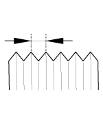
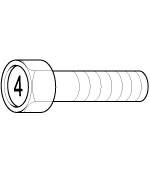
| BOLT/NUT Thin screw | Torque Nm (kg.m, Ib-ft) | |||
| Nominal diameter. (mm) | Pitch [mm (in.) ] | 4T | 8T | 10T |
|
|
|
| |
| M5 | 0.5 (0.019) | 2.0 ~ 3.0 (0.2 ~ 0.3, 1.4 ~ 2.2) | 5.9 ~ 8.8 (0.6 ~ 0.9, 4.3 ~ 6.5) | 8.8 ~ 12.7 (0.9 ~ 1.3, 6.5 ~ 9.4) |
| M6 | 0.75 (0.029) | 3.9 ~ 4.9 (0.4 ~ 0.5, 2.9 ~ 3.6) | 9.8 ~ 13.7 (1.0 ~ 1.4, 7.2 ~ 10.1) | 14.7 ~ 20.6 (1.5 ~ 2.1, 10.8 ~ 15.2) |
| M8 | 1 (0.039) | 8.8 ~ 11.8 (0.9 ~ 1.2, 6.5 ~ 8.7) | 24.5 ~ 32.4 (2.5 ~ 3.3, 18.1 ~ 23.9) | 35.3 ~ 48.1 (3.6 ~ 4.9, 26.0 ~ 35.4) |
| M10 | 1.25 (0.049) | 17.7 ~ 23.5 (1.8 ~ 2.4, 13.0 ~ 17.4) | 47.1 ~ 63.7 (4.8 ~ 6.5, 34.7 ~ 47.0) | 69.6 ~ 94.1 (7.1 ~ 9.6, 51.4 ~ 69.4) |
| M12 | 1.25 (0.049) | 32.4 ~ 44.1 (3.3 ~ 4.5, 23.9 ~ 32.5) | 86.3 ~ 117.7 (8.8 ~ 12.0, 63.7 ~ 86.8) | 127.5 ~ 172.6 (13.0 ~ 17.6, 94.0 ~ 127.3) |
| M14 | 1.5 (0.059) | 51.0 ~ 69.6 (5.2 ~ 7.1, 37.6 ~ 51.4) | 136.3 ~ 185.3 (13.9 ~ 18.9, 100.5 ~ 136.7) | 201.0 ~ 271.6 (20.5 ~ 27.7, 148.3 ~ 200.4) |
| M16 | 1.5 (0.059) | 79.4 ~ 107.9 (8.1 ~ 11.0, 58.6 ~ 79.6) | 211.8 ~ 286.4 (21.6 ~ 29.2, 156.2 ~ 211.2) | 311.8 ~ 421.7 (31.8 ~ 43.0, 230.0 ~ 311.0) |
| M20 | 1.5 (0.059) | 163.8 ~ 221.6 (16.7 ~ 22.6, 120.8 ~ 163.5) | 448.2 ~ 607.0 (45.7 ~ 61.9, 330.5 ~ 447.7) | 639.4 ~ 864.9 (65.2 ~ 88.2, 471.6 ~ 638.0) |
| M24 | 2 (0.078) | 276.5 ~ 373.6 (28.2 ~ 38.1, 204.0 ~ 275.6) | 759.0 ~ 1026.8 (77.4 ~ 104.7, 559.8 ~ 757.3) | 1080.7 ~ 1462.2 (110.2 ~ 149.1, 797.1 ~ 1078.4) |
| M30 | 2 (0.078) | 562.9 ~ 762.0 (57.4 ~ 77.7, 415.2 ~ 562.0) | 1553.4 ~ 2102.5 (158.4 ~ 214.4, 1145.7 ~ 1550.8) | 2210.4 ~ 2991.0 (225.4 ~ 305.0, 1630.3 ~ 2206.1) |
| Flange BOLT (Nominal diameter) | Flange NUT (Nominal diameter) | ||
|
|
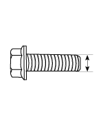
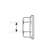
| Flange BOLT/NUT Normal screw | Torque Nm (kg.m, Ib-ft) | |||
| Nominal diameter. (mm) | Pitch [mm (in.) ] | 4T | 8T | 10T |
|
|
|
| |
| M5 | 0.8 (0.031) | 2.0 ~ 2.9 (0.2 ~ 0.3, 1.4 ~ 2.2) | 5.9 ~ 7.8 (0.6 ~ 0.8, 4.3 ~ 5.8) | 8.8 ~ 11.8 (0.9 ~ 1.2, 6.5 ~ 8.7) |
| M6 | 1 (0.039) | 3.9 ~ 4.9 (0.4 ~ 0.5, 2.9 ~ 3.6) | 9.8 ~ 13.7 (1.0 ~ 1.4, 7.2 ~ 10.1) | 14.7 ~ 19.6 (1.5 ~ 2.0, 10.8 ~ 14.5) |
| M8 | 1.25 (0.049) | 8.8 ~ 11.8 (0.9 ~ 1.2, 6.5 ~ 8.7) | 24.5 ~ 32.4 (2.5 ~ 3.3, 18.1 ~ 23.9) | 35.3 ~ 48.1 (3.6 ~ 4.9, 26.0 ~ 35.4) |
| M10 | 1.5 (0.059) | 17.7 ~ 24.5 (1.8 ~ 2.5, 13.0 ~ 18.1) | 48.1 ~ 65.7 (4.9 ~ 6.7, 35.4 ~ 48.5) | 70.6 ~ 96.1 (7.2 ~ 9.8, 52.1 ~ 70.9) |
| M12 | 1.75 (0.068) | 31.4 ~ 43.1 (3.2 ~ 4.4, 23.1 ~ 31.8) | 84.3 ~ 113.8 (8.6 ~ 11.6, 62.2 ~ 83.9) | 123.6 ~ 167.7 (12.6 ~ 17.1, 91.1 ~ 123.7) |
| M14 | 2 (0.078) | 51.0 ~ 68.6 (5.2 ~ 7.0, 37.6 ~ 50.6) | 135.3 ~ 182.4 (13.8 ~ 18.6, 99.8 ~ 134.5) | 198.1 ~ 268.7 (20.2 ~ 27.4, 146.1 ~ 198.2) |
| M16 | 2 (0.078) | 79.4 ~ 107.9 (8.1 ~ 11.0, 58.6 ~ 79.6) | 212.8 ~ 288.3 (21.7 ~ 29.4, 157.0 ~ 212.7) | 311.8 ~ 421.7 (31.8 ~ 43.0, 230.0 ~ 311.0) |
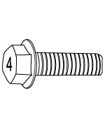
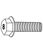
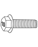
| Flange BOLT/NUT Thin screw | Torque Nm (kg.m, Ib-ft) | |||
Nominal diameter. (mm) | Pitch [mm (in.) ] | 4T | 8T | 10T |
|
|
|
| |
| M5 | 0.5 (0.019) | 2.9 ~ 2.9 (0.3 ~ 0.3, 2.2 ~ 2.2) | 6.9 ~ 8.8 (0.7 ~ 0.9, 5.1 ~ 6.5) | 9.8 ~ 13.7 (1.0 ~ 1.4, 7.2 ~ 10.1) |
| M6 | 0.75 (0.029) | 3.9 ~ 5.9 (0.4 ~ 0.6, 2.9 ~ 4.3) | 10.8 ~ 14.7 (1.1 ~ 1.5, 8.0 ~ 10.8) | 16.7 ~ 21.6 (1.7 ~ 2.2, 12.3 ~ 15.9) |
| M8 | 1 (0.039) | 9.8 ~ 12.7 (1.0 ~ 1.3, 7.2 ~ 9.4) | 26.5 ~ 35.3 (2.7 ~ 3.6, 19.5 ~ 26.0) | 38.2 ~ 52.0 (3.9 ~ 5.3, 28.2 ~ 38.3) |
| M10 | 1.25 (0.049) | 19.6 ~ 25.5 (2.0 ~ 2.6, 14.5 ~ 18.8) | 51.0 ~ 68.6 (5.2 ~ 7.0, 37.6 ~ 50.6) | 75.5 ~ 102.0 (7.7 ~ 10.4, 55.7 ~ 75.2) |
| M12 | 1.25 (0.049) | 35.3 ~ 48.1 (3.6 ~ 4.9, 26.0 ~ 35.4) | 94.1 ~ 126.5 (9.6 ~ 12.9, 69.4 ~ 93.3) | 138.3 ~ 186.3 (14.1 ~ 19.0, 102.0 ~ 137.4) |
| M14 | 1.5 (0.059) | 55.9 ~ 75.5 (5.7 ~ 7.7, 41.2 ~ 55.7) | 148.1 ~ 200.1 (15.1 ~ 20.4, 109.2 ~ 147.6) | 216.7 ~ 293.2 (22.1 ~ 29.9, 159.8 ~ 216.3) |
| M16 | 1.5 (0.059) | 86.3 ~ 116.7 (8.8 ~ 11.9, 63.7 ~ 86.1) | 229.5 ~ 309.9 (23.4 ~ 31.6, 169.3 ~ 228.6) | 336.4 ~ 455.0 (34.3 ~ 46.4, 248.1 ~ 335.6) |
|


See also:
Repair procedures
Fuel Pressure Test
1.
Release the residual pressure in fuel line.
(Refer to Fuel Delivery System - “Release Residual Pressure in Fuel Line�)
When removing the fuel pum ...
Storage compartments
These compartments can be used to store small items required by the driver or
passengers.
CAUTION
To avoid possible theft, do not leave valuables in the storage compartments.
Always keep the s ...
Heated Oxygen Sensor (HO2S) Repair procedures
Inspection
1.
Turn the ignition switch OFF.
2.
Disconnect the HO2S connector.
3.
Measure resistance between the HO2S terminals 3 and 4.
4.
Check that the resistance is within the speci ...
Categories
Hyundai Azera Manuals

© 2011-2026 Copyright www.hgmanual.com