 Hyundai Azera: Transaxle Control Module (TCM) Schematic Diagrams
Fifth generation HG (2011–2026) / Hyundai Azera 2011-2026 Service Manual / Automatic Transaxle System / Automatic Transaxle Control System / Transaxle Control Module (TCM) Schematic Diagrams
Hyundai Azera: Transaxle Control Module (TCM) Schematic Diagrams
Fifth generation HG (2011–2026) / Hyundai Azera 2011-2026 Service Manual / Automatic Transaxle System / Automatic Transaxle Control System / Transaxle Control Module (TCM) Schematic Diagrams
Fifth generation HG (2011–2026) / Hyundai Azera 2011-2026 Service Manual / Automatic Transaxle System / Automatic Transaxle Control System / Transaxle Control Module (TCM) Schematic Diagrams
| TCM connector and terminal function |
| TCM Terminal Function |
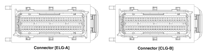
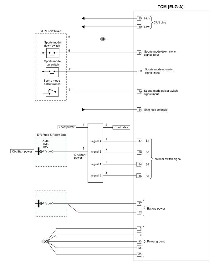
Connector [ELG-A]
| Pin | Description | Pin | Description |
| 1 | ? | 51 | ? |
| 2 | ? | 52 | ? |
| 3 | ? | 53 | ? |
| 4 | ? | 54 | Sports mode down switch |
| 5 | ? | 55 | ? |
| 6 | ? | 56 | ? |
| 7 | ? | 57 | ? |
| 8 | ? | 58 | ? |
| 9 | CCP CAN(HIGH) | 59 | ? |
| 10 | CAN Communication line(HIGH) | 60 | ? |
| 11 | ? | 61 | ? |
| 12 | ? | 62 | ? |
| 13 | ? | 63 | ? |
| 14 | ? | 64 | ? |
| 15 | ? | 65 | ? |
| 16 | ? | 66 | ? |
| 17 | ? | 67 | ? |
| 18 | ? | 68 | ? |
| 19 | ? | 69 | ? |
| 20 | ? | 70 | ? |
| 21 | ? | 71 | ? |
| 22 | ? | 72 | ? |
| 23 | ? | 73 | ? |
| 24 | ? | 74 | ? |
| 25 | ? | 75 | ? |
| 26 | ? | 76 | ? |
| 27 | ? | 77 | ? |
| 28 | ? | 78 | ? |
| 29 | Sports mode up switch | 79 | Sports mode select switch |
| 30 | ? | 80 | ? |
| 31 | ? | 81 | ? |
| 32 | ? | 82 | ? |
| 33 | ? | 83 | ? |
| 34 | CCP CAN(LOW) | 84 | Shift lock solenoid |
| 35 | CAN Communication line(LOW) | 85 | ? |
| 36 | ? | 86 | ? |
| 37 | ? | 87 | ? |
| 38 | ? | 88 | ? |
| 39 | ? | 89 | ? |
| 40 | ? | 90 | ? |
| 41 | ? | 91 | ? |
| 42 | ? | 92 | ? |
| 43 | ? | 93 | ? |
| 44 | Inhibitor switch signal "S1" | 94 | ? |
| 45 | Inhibitor switch signal "S2" | 95 | ? |
| 46 | Inhibitor switch signal "S3" | 96 | ? |
| 47 | Inhibitor switch signal "S4" | 97 | ? |
| 48 | ? | 98 | ? |
| 49 | ? | 99 | ? |
| 50 | ? | 100 | ? |
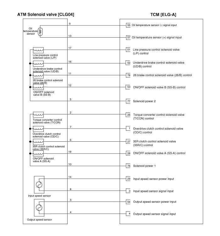
Connector [CLG-B]
| Pin | Description | Pin | Description |
| 1 | Overdrive clutch control solenoid valve (OD/C) | 51 | Line pressure control solenoid valve (L/P) |
| 2 | ? | 52 | Underdrive brake control solenoid valve (UD/B) |
| 3 | Input speed sensor signal | 53 | ON/OFF solenoid valve B(SS-B) |
| 4 | Output speed sensor signal | 54 | Output speed sensor power |
| 5 | ? | 55 | Oil temperature sensor (+) |
| 6 | ? | 56 | ? |
| 7 | ? | 57 | Oil temperature sensor (-) |
| 8 | ? | 58 | ? |
| 9 | ? | 59 | ? |
| 10 | ? | 60 | ? |
| 11 | ? | 61 | ? |
| 12 | ? | 62 | ? |
| 13 | ? | 63 | ? |
| 14 | ? | 64 | ? |
| 15 | ? | 65 | ? |
| 16 | ? | 66 | ? |
| 17 | ? | 67 | ? |
| 18 | ? | 68 | ? |
| 19 | ? | 69 | ? |
| 20 | ? | 70 | ? |
| 21 | ? | 71 | ? |
| 22 | ? | 72 | ? |
| 23 | ? | 73 | ? |
| 24 | ? | 74 | ? |
| 25 | ? | 75 | ? |
| 26 | Torque converter control solenoid valve (T/CON) | 76 | Solenoid supply power 1 |
| 27 | 35R Clutch control solenoid valve (35R/C) | 77 | Solenoid supply power 2 |
| 28 | ON/OFF solenoid valve A (SS-A) | 78 | 26 brake control solenoid valve (26/B) |
| 29 | Input speed sensor power | 79 | ? |
| 30 | ? | 80 | ? |
| 31 | ? | 81 | ? |
| 32 | ? | 82 | ? |
| 33 | ? | 83 | ? |
| 34 | ? | 84 | ? |
| 35 | ? | 85 | ? |
| 36 | ? | 86 | ? |
| 37 | ? | 87 | ? |
| 38 | ? | 88 | ? |
| 39 | ? | 89 | ? |
| 40 | ? | 90 | ? |
| 41 | ? | 91 | ? |
| 42 | ? | 92 | ? |
| 43 | ? | 93 | ? |
| 44 | ? | 94 | ? |
| 45 | ? | 95 | ? |
| 46 | ? | 96 | ? |
| 47 | ? | 97 | ? |
| 48 | ? | 98 | ? |
| 49 | ? | 99 | ? |
| 50 | ? | 100 | ? |
| TCM Terminal input/ output signal |
Connector[ELG-A]
| Pin | Description | Condition | Input/output value | |
| Type | Level | |||
| 10 | CAN Communication line(HIGH) | - | - | - |
| 29 | Sports mode up switch | Up ON | Input | 0V/Battery voltage level |
| Other | 9V < Battery voltage level <16V | |||
| 35 | CAN Communication line(LOW) | - | - | - |
| 44 | Inhibitor switch signal "S1" | ON | Input | Battery voltage level |
| OFF | 9V < Battery voltage level <16V | |||
| 45 | Inhibitor switch signal "S2" | ON | Input | Battery voltage level |
| OFF | 9V < Battery voltage level <16V | |||
| 46 | Inhibitor switch signal "S3" | ON | Input | Battery voltage level |
| OFF | 9V < Battery voltage level <16V | |||
| 47 | Inhibitor switch signal "S4" | ON | Input | Battery voltage level |
| OFF | 9V < Battery voltage level <16V | |||
| 54 | Sports mode down switch | Up ON | Input | 0V/Battery voltage level |
| Other | 9V < Battery voltage level <16V | |||
| 79 | Sports mode select switch | Sport mode | Input | 0V/Battery voltage level |
| Other | 9V < Battery voltage level <16V | |||
| 84 | Shift lock solenoid | - | - | - |
Connector [CLG-B]
| Pin | Description | Condition | Input/output value | |
| Type | Level | |||
| 1 | Overdrive clutch control solenoid valve (OD/C) | - | Output | 0V/Battery voltage level |
| 9V < Battery voltage level <16V | ||||
| 3 | Input speed sensor signal | Rotate | Pulse | Maximum frequency : 9 kHz |
| Minimum frequency : > 0 Hz | ||||
| 4 | Output speed sensor signal | Rotate | Pulse | Minimum high pulse : ? 25 ? |
| Minimum low pulse : ? 25 ? | ||||
| 26 | Torque converter control solenoid valve (T/CON) | - | Output | 0V/Battery voltage level |
| 9V < Battery voltage level <16V | ||||
| 27 | 35R Clutch control solenoid valve (35R/C) | - | Output | 0V/Battery voltage level |
| 9V < Battery voltage level <16V | ||||
| 28 | ON/OFF solenoid valve A (SS-A) | - | Output | 0V/Battery voltage level |
| 9V < Battery voltage level <16V | ||||
| 29 | Input speed sensor power | ON | Power | 0V/7.5V |
| OFF | ||||
| 51 | Line pressure control solenoid valve (L/P) | - | Output | 0V/Battery voltage level |
| 9V < Battery voltage level <16V | ||||
| 52 | Underdrive brake control solenoid valve (UD/B) | - | Output | 0V/Battery voltage level |
| 9V < Battery voltage level <16V | ||||
| 53 | ON/OFF solenoid valve B (SS-B) | - | Output | 0V/Battery voltage level |
| 9V < Battery voltage level <16V | ||||
| 54 | Output speed sensor power | ON | Power | 0V/7.5V |
| OFF | ||||
| 55 | Oil temperature sensor (+) | - | Input | 5V |
| 57 | Oil temperature sensor (-) | - | Ground | 0V |
| 76 | Solenoid supply power 1 | - | Power | Battery voltage level |
| 9V < Battery voltage level <16V | ||||
| 77 | Solenoid supply power 2 | - | Power | Battery voltage level |
| 9V < Battery voltage level <16V | ||||
| 78 | 26 Brake control solenoid valve (26/B) | - | Output | 0V/Battery voltage level |
| 9V < Battery voltage level <16V | ||||
| Circuit Diagram |
 Transaxle Control Module (TCM) Description and Operation
Description
Transaxle Control Module (TCM) is the automatic transaxle's
brain. The module receives and processes signals from various sensors
and implements a wide range of transaxle controls t ...
 Transaxle Control Module (TCM) Repair procedures
Inspection
Transaxle Control Module(TCM) Problem Inspection Procedure
1.
TEST TCM GROUND CIRCUIT: Measure resistance between TCM and
chassis ground using the backside of TCM harness connector a ...
See also:
TPMS Receiver Repair procedures
Replacement
When the receiver first arrives for replacement:
1)
It will be in Virgin State.
2)
It will not be configured for any specific platform.
3)
It will not ha ...
AVN Head Unit Components and Components Location
Components
AVN (A/V & Navigation) Head Unit Connector
Pin No.DescriptionCommentsA1--A2PARKING_V_VIDEORear View Camera Video SignalA3PARKING_V_GNDRear View Camera Video GroundA4R/C_SHIELD G ...
Thermostat Troubleshooting
Troubleshooting
SymptomsPossible CausesRemedyCoolant leakage
•
From the thermostat gasket
Check the mounting bolts
•
Check the torque of the mounting bolts
•
Retighten the bo ...
Categories
Hyundai Azera Manuals

© 2011-2026 Copyright www.hgmanual.com