
 Hyundai Azera: Rear Disc Brake Repair procedures
Fifth generation HG (2011–2026) / Hyundai Azera 2011-2026 Service Manual / Brake System / Brake System / Rear Disc Brake Repair procedures
Hyundai Azera: Rear Disc Brake Repair procedures
Fifth generation HG (2011–2026) / Hyundai Azera 2011-2026 Service Manual / Brake System / Brake System / Rear Disc Brake Repair procedures
Fifth generation HG (2011–2026) / Hyundai Azera 2011-2026 Service Manual / Brake System / Brake System / Rear Disc Brake Repair procedures
| Removal |
| 1. |
Remove the rear wheel & tire.
|
| 2. |
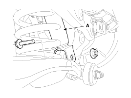
Loosen the bolt & nut and then disconnect the shock absorber (A) with the rear axle.
|

| 3. |
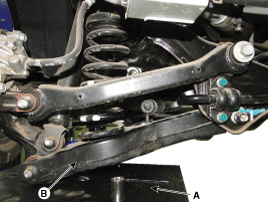
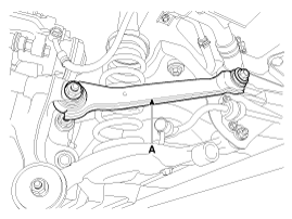
Remove the rear upper arm (A).
|
| 4. |
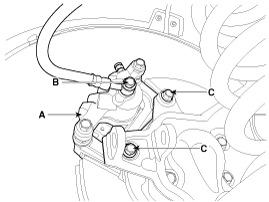
Loosen the hose eyebolt (B) and caliper mounting bolts (C), then remove the rear caliper assembly (A).
|
| 5. |
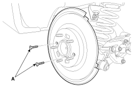
Remove the rear brake disc by loosening the screws (A).
|
| Replacement |
| 1. |
Remove the rear wheel & tire. |
| 2. |
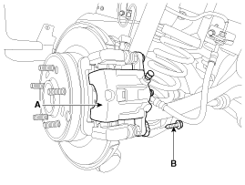
Loosen the guide rod bolt (B) and pivot the caliper (A) up out of the way.
|
| 3. |
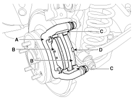
Replace pad shim (D), pad retainers (C) and brake pads (B) in the caliper carrier (A).
|
| 4. |
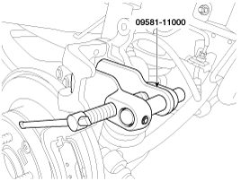
Use a SST (09581-11000) when installing the brake caliper assembly.
|
| 5. |
Place the caliper body (A) on the caliper carrier and tighten the guide rod bolts (B).
|
| 6. |
Install the rear wheel & tire.
|
| Inspection |
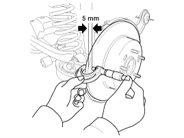
Rear Brake Disc Thickness Check
| 1. |
Check the brake pads for wear and fade. |
| 2. |
Check the brake disc for damage and cracks. |
| 3. |
Remove all rust and contamination from the surface, and
measure the disc thickness at 8 points, at least, of same distance (5mm)
from the brake disc outer circle.
|
| 4. |
If wear exceeds the limit, replace the discs and pad assembly left and right of the vehicle. |
Rear Brake Pad Check
| 1. |
Check the pad wear. Measure the pad thickness and replace it, if it is less than the specified value.
|
| 2. |
Check that grease is applied, to sliding contact points and the pad and backing metal for damage.
|
Rear Brake Disc Runout Check
| 1. |
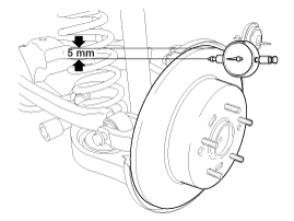
Place a dial gauge about 5mm (0.2 in.) from the outer circumference of the brake disc, and measure the runout of the disc.
|
| 2. |
If the runout of the brake disc exceeds the limit specification, replace the disc, and then measure the runout again. |
| 3. |
If the runout exceeds the limit specification, install the
brake disc after turning it 180° and then check the runout of the brake
disc again. |
| 4. |
If the runout cannot be corrected by changing the position of the brake disc, replace the brake disc. |
| Installation |
| 1. |
Installation is the reverse of removal. |
| 2. |
Use a SST (09581-11000) when installing the brake caliper assembly.
|
| 3. |
After installation, bleed the brake system.
(Refer to Brake system bleeding) |
 Rear Disc Brake Components and Components Location
Components
1. Guide rod bolt2. Bleed screw3. Caliper carrier4. Caliper body5. Inner pad shim6. Brake pad7. Pad retainer
...
 Brake Switch Repair procedures
Removal
1.
Turn ignition switch OFF and disconnect the negative (-) battery cable.
2.
Remove the lower crash pad.
(Refer to the Body - "Crash Pad")
3.
Disconnect the stop lamp switch con ...
See also:
Cylinder Block Repair procedures
Disassembly
•
Use fender covers to avoid damaging painted surfaces.
•
To avoid damage, unplug the wiring connectors carefully while holding the connector portion. ...
Head Lamps Components and Components Location
Component
1. Head lamp assembly & housing2. Dust cap3. Head lamp(Low) bulb4. Head lamp(High) bulb5. Turn signal lamp bulb
1. Head lamp assembly lens & housing2. Head lamp(High) bulb3 ...
Steering Gear box Components and Components Location
Components
1. Tie-rod end2. Lock nut3. Bellows clip4. Bellows5. Tie rod6. Rack bar7. Dust packing8. Dust cap9. Oil seal10. Pinion plug11. Pinion assembly12. Yoke plug13. Yoke spring14. Support yo ...
Categories
Hyundai Azera Manuals

© 2011-2026 Copyright www.hgmanual.com